I.L. 15579B
Page 3
Effective 12/98
torque loading. Torque values for line/load terminals
are given in Tables 2.1 and 2.2 and on the MCP name-
plate.
3-0 MANUAL OPERATION
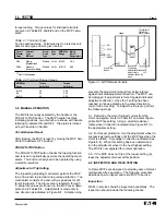
The MCP is manually operated by the handle or the
PUSH-TO-TRIP button. The MCP handle has three
indicating positions, two of which are shown with handle
lettering to indicate ON and OFF. Trip status is indicat-
ed by white strip on handle.
Circuit Breaker Reset
After tripping, the MCP is reset by moving the MCP han-
dle to the extreme OFF position.
PUSH-TO-TRIP Button
The PUSH-TO-TRIP button checks the tripping function
and is used to periodically exercise the operating mech-
anism. The button is designed to be operated by using
a small screwdriver.
Adjustment of Trip Setting
The trip setting adjusting mechanism permits the MCP
to be fine tuned to provide more precise protection. The
mechanism consists of a cam with six positions for dif-
ferent trip levels. The trip levels are labeled A through
F; actual trip values are shown on the MCP cover name-
plate and in Tables 3.1. Adjustments is made only in
one direction as indicated in Figure 3-1. A rotation stop
prevents the adjustment wheel from being rotated
against indicated adjustment direction. The MCP can
be damaged if adjustment is forced against indicated
adjustment direction. Once the F setting has been
reached, continue adjusting in the same direction to
return to the A setting. To adjust the trip level, perform
the following steps:
3-1. Determine the motor full load current from the
motor nameplate. Refer to Table 3.1 and select appro-
priate MCP trip setting. Using a small screwdriver,
rotate wheel in direction indicated (See Figure 3-1) to
the appropriate setting.
3-2. For closest protection, turn the adjustment wheel to
successively lower settings until the MCP trips when the
motor is started. Only adjust in direction indicated (See
Figure 3-1). When this setting has been determined,
turn the adjustment wheel to the next highest setting.
The MCP is now adjusted for normal operation.
3-3. If the MCP does not trip at the lowest setting (A),
leave the adjustment wheel at this position.
4-0 INSPECTION AND FIELD TESTING
G-Frame MCPs are designed to provide years of almost
maintenance-free operation. The following procedure
describes how to inspect and test a MCP in service.
Inspection
MCPs in service should be inspected periodically. The
inspection should include the following checks:
Circuit Terminal
Screw
Wire
AWG
Wire Metric
Breaker
Type
Head
Type Range
Wire
➀
Amps.
Material
Type
Range (mm
2
)
3-20
Clamp
Slotted
Cu/Al
#14-10
1.5-4
(Plated Steel)
25-63
Pressure
Slotted Cu/Al
#10-1/0
4-50
(Aluminum Body)
➀
Not UL Listed sizes.
Table 2.1 Terminal Types
For line and load-side. Terminals are UL Listed as suit-
able for wire type and size given below.
AWG Wire
Torque
Torque
Range
Value lb-in
Value N.m.
#14-10
20
2.26
#8
40
4.52
#6-1/0
45
5.09
Table 2.2 Terminal Torque Values
Figure 3-1 MCP Manual Controls
Handle
Trip Indicator:
White Color
When Tripped
ON
TRIP
OFF
RESET
Push to Trip
Button
Trip Setting
Adjustment Mechanism
Adjust Only In
Direction Shown By
Arrow


