background image


12 

                                  GROUNDING INSTRUCTIONS (cont.)                             


Make certain the extension cord is properly sized, and in good electrical condition. Always replace 

a worn or damaged extension cord immediately or have it repaired by a qualified person before 

using it. 


Protect your extension cords from sharp objects, excessive heat, and damp or wet areas. 


MINIMUM RECOMMENDED GAUGE FOR EXTENSION CORDS (AWG) 

115 VOLT OPERATION ONLY 


25’ LONG 

50’ LONG 

100’ LONG 

150’ LONG 

0 to 6 Amps 

18 AWG 

16 AWG 

16 AWG 

14 AWG 

6 to 10 Amps 

18 AWG 

18 AWG 

14 AWG 

12 AWG 

10 to 12 Amps 

16 AWG 

16 AWG 

14 AWG 

12 AWG 


Содержание 40100-CT

Страница 1: ...this manual before using machine to avoid serious injury and damage 40300H CT 13 PORTABLE PLANER with Spiral Style Cutterhead For technical support email techservices cutechtool com or call at 877 568 8879 VER 15 07 07 ...

Страница 2: ...13 Parts List 27 INTRODUCTION This user manual is intended for use by anyone working with this machine It should be kept available for immediate reference so that all operations can be performed with maximum efficiency and safety Do not attempt to perform maintenance or operate this machine until you have read and understand the information contained in this manual The drawings illustrations photo...

Страница 3: ... returned Freight prepaid to CUTECH s Authorized Service Center for inspection If the warranty claim is considered to be invalid due to exclusions listed above CUTECH will at your direction dispose of or return the product In the event you choose to have the product returned you will be responsible for the handling and shipping cost of the return CUTECH furnishes the above warranties in lieu of al...

Страница 4: ...ity 6 x 13 Max depth of cut 6 1 8 Max depth of cut 13 1 16 Minimum Length of Stock 7 Minimum Thickness of Stock 1 8 Cutter inserts qty 26 2 sided Motor power input 115 V 60 Hz AC Only 15 Amp Shipping Weight 66lbs Shipping Dimensions 24 W x 16 D x 20 H Product Dimensions 21 1 2 W x 28 3 16 D w tables x 19 H w o handle Dust Port Opening 2 or 4 ...

Страница 5: ...5 FEATURE IDENTIFICATION Infeed Table Thickness Scale Power Switch Raise Lower Handle Depth of Cut Indicator Dust Port Quick Set Indicator ...

Страница 6: ...jury including silicosis a serious lung disease cancer and death Avoid breathing the dust and avoid prolonged contact with dust The dust may contain chemicals known to the State of California to cause cancer birth defects or other reproductive harm Some examples of these chemicals are Lead from lead based paints Crystalline silica from bricks cement and other masonry products Arsenic and chromium ...

Страница 7: ...er quality job by only performing operations for which the machine was intended WARNING DO NOT stand on a machine Serious injury could result if it tips over or you accidentally contact any moving part DO NOT store anything above or near the machine WARNING DO NOT operate any machine or tool if under the influence of drugs alcohol or medication EACH AND EVERY time check for damaged parts prior to ...

Страница 8: ...SE ONLY recommended accessories Use of incorrect or improper accessories could cause serious injury to the operator and cause damage to the machine If in doubt DO NOT use it THE USE of extension cords is not recommended for 230V equipment It is better to arrange the placement of your equipment and the installed wiring to eliminate the need for an extension cord If an extension cord is necessary re...

Страница 9: ...tions and wiring should be made by qualified personnel only 4 WARNING TO REDUCE the risk of electrical shock DO NOT use this machine outdoors DO NOT expose to rain Store indoors in a dry area 5 STOP using this machine if at any time you experience difficulties in performing any operation Contact your supervisor instructor or machine service center immediately 6 Safety decals are on this machine to...

Страница 10: ...amaged blades 19 MAKE CERTAIN that the planer is properly adjusted prior to use 20 DO NOT try and remove excessive amounts of wood in one single pass 21 INSPECT all stock before planing ensuring that there are no foreign objects embedded in the wood loose knots or knots that may become loose during operation 22 WARNING DO NOT attempt to remove jams until power is disconnected and all moving parts ...

Страница 11: ...ou are not sure the tool is properly grounded WARNING Electrocution or fire could result if this machine is not grounded properly or if the electrical configuration does not comply with local and state electrical codes MAKE CERTAIN the machine is disconnected from power source before starting any electrical work MAKE SURE the circuit breaker does not exceed the rating of the plug and receptacle Th...

Страница 12: ... or have it repaired by a qualified person before using it Protect your extension cords from sharp objects excessive heat and damp or wet areas MINIMUM RECOMMENDED GAUGE FOR EXTENSION CORDS AWG 115 VOLT OPERATION ONLY 25 LONG 50 LONG 100 LONG 150 LONG 0 to 6 Amps 18 AWG 16 AWG 16 AWG 14 AWG 6 to 10 Amps 18 AWG 18 AWG 14 AWG 12 AWG 10 to 12 Amps 16 AWG 16 AWG 14 AWG 12 AWG ...

Страница 13: ...otective coatings are removed completely After cleaning apply a good quality paste wax to any unpainted surfaces including the infeed outfeed and center tables Make sure to buff out the wax before assembly Compare the items to inventory figures and verify that all items are accounted for If at all possible retain shipping carton for warranty service if ever needed If any parts are missing do not a...

Страница 14: ...d fasten in place with 1 Hex Socket Head screw Tighten screw using supplied hex wrench SEE FIG 1 FIG 1 ATTACHING DUST PORT The Dust Port is to be used when the planer to be connected to a dust collector It has a dual 2 and 4 port on it to accommodate most dust collection systems To install 1 Install the dust port in the rear of the planer by using 4 socket head cap screws SEE FIG 2 ...

Страница 15: ...any tendency for the planer to tip over slide or walk the planer MUST be secured to a supporting surface such as a workbench or table Four holes are provided 2 are shown at A to securely mount the planer The surface you are mounting the planer to should be perfectly flat SEE FIG 3 FIG 3 ...

Страница 16: ...n the planer table C with one end of the straight edge over the infeed table B SEE FIG 4 2 Check to make sure that the infeed table is level with the planer table 3 If an adjustment is necessary raise table loosen lock nuts D and adjust Hex Head Screws E on each side of the table until the infeed table is level with the planer table This will adjust the outer edge of the table 4 Recheck for level ...

Страница 17: ...terhead up or down approximately 1 16 You can confirm this by referencing the scale C on the front right side of the planer FIG 5 NOTE The Quick Set Thickness Indicator D located on the bottom right side of the planer provides a simple way to preset the finished thickness of a workpiece The indicator can be set to 1 8 1 4 1 2 or 3 4 Rotate the wheel of the indicator to the desired finished thickne...

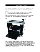
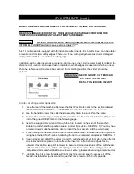
Страница 18: ...on for information on removal 2 Use the handle to lower the cutterhead assembly down to about 2 on the scale 3 Remove the cutterhead guard A by removing the Hex Soc Head Cap Screws B on each end of the guard SEE FIG 6 on the following page 4 Insert the supplied Hex wrench through the hole located on the side of the machine Rotate the cutterhead to a position where a cutter tip is visible SEE FIG 7...

Страница 19: ...THICKNESS SCALE ADJUSTMENT The thickness scale located on the right of the planer shows the thickness of the finished workpiece To make sure the scale is set properly run a piece of wood through the planer and measure the thickness of the wood If the scale is out of alignment loosen the two round head screws A holding the scale indicator B and adjust the thickness indicator to the correct setting ...

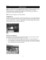
Страница 20: ... position This planer is also equipped with a special lockout toggle switch that prevents unauthorized use To prevent unauthorized use of the planer simply pull out the yellow key A located on the face of the switch SEE FIG 9 FIG 9 DEPTH OF CUT INDICATOR The Depth Of Cut Indicator located on the front of the machine is a convenient way to quickly determine how much material is being planed off in ...

Страница 21: ...to the desired finished thickness Use this feature when thickness planing multiple workpieces to ensure a uniform thickness of all workpieces See the following figure FIG 11 NOTE When lowering the head assembly ensure the quick set thickness indicator is in the lowest desired thickness position Failure to do so may result in excess downward pressure by the cutterhead assembly onto the Quick Set me...

Страница 22: ...lers have engaged 4 Move to one side of the rear of the planer and receive the planed workpiece by grabbing the edges of the wood like you did when feeding the workpiece in 6 It normally takes several passes of varying depths to achieve a smooth finish so repeat this process as many times as necessary Remember the less you take off in a pass the smoother the finish will be Finish the surface by sa...

Страница 23: ...buildup and other debris can cause the tool to plane incorrectly Periodic cleaning and waxing is needed for accurate precision planing Any moving parts should be cleaned regularly with a penetrating oil and lubricated with a light coating of medium weight machine oil CAUTION With the machine unplugged blow off motor with low pressure air to remove dust or dirt Air pressure above 50 P S I should no...

Страница 24: ...ove the 9 screws holding the top cover on the machine 5 screws are located on top and 4 on the upper sides Remove the top cover 3 On the left side panel remove the 3 socket head screws located around the bottom edge and remove the side panel to expose the gearbox cover SEE FIG 12 FIG 12 4 Remove the two screws C to remove the gear box cover B and access the gear box SEE FIG 13 FIG 13 ...

Страница 25: ... that you removed once lubrication is complete BRUSH REPLACEMENT Brush life will vary depending on the load placed on the motor The brushes should be inspected every 10 15 hours of use To inspect or replace 1 Remove the brush holders one of which is shown at A The other is located in the same position on the rear of the motor assembly The Brush Holder can be removed using a flat blade screwdriver ...

Страница 26: ...FIG 16 3 If the carbon of either brush is worn down to 3 16 or less both brushes should be replaced Also if the spring or wire are burned or damaged in any way both brushes should be replaced BLADE INSERT REPLACEMENT For information on replacing cutter inserts refer to the ADJUSTMENTS section page 17 of this manual ...

Страница 27: ...ure content Dull blades Too deep a blade setting Dry wood before planing Replace or turn blades Reduce depth of cut Board thickness does not match depth scale indicator Depth scale incorrectly set Adjust depth scale Will not start Not plugged in Blown circuit Lockout key removed Check the power source Replace fuse reset breaker or call electrician Replace lockout key Interrupted operation Unit ove...

Страница 28: ...28 PARTS ...

Страница 29: ...29 ...

Страница 30: ...30 ...

Страница 31: ...TION NUT 4 48 SPRING WASHER 4 19 RIGHT SIDE COVER T 1 0mm 1 49 TABLE BUSHING 4 20 SCALE t 0 3mm 1 50 PAN HD SCR M6xP1 0x16L 4 21 HEIGHT ADJ SPINDLE 1 51 INFEED OUTFEED TABLE 319 230 2 22 SPECIAL BOLT M6xP1 0 1 52 ROLLER CHAIN 1 23 TURNNING TRAY 1 53 HEX HD SCREW M8xP1 25x45L 1 24 STEEL BALL 10 1 54 HEX NUT M8xP1 25 1 25 COIL SPRING 7 62x 15 75x0 7t 1 55 FLAT WASHER 4 26 WEAR PLATE 1 56 BELT GUARD ...

Страница 32: ... 82 CURSOR H 15 1 111 HEX SOC HD SCR M5xP0 8x27L 2 83 PAN HD SCR M3xP0 5x15L 2 112 HEX SOC HD SCR M5xP0 8x35L 2 84 PAN HD SCR L WASH M5xP0 8x10L 2 113 SPROCKET 8T 4 85 EXT TOOTH WASHER 5 2 114 RING EXT RET STW15 3 86 PAN HD SCR M4xP0 7x12L 3 115 GEARBOX DRIVE CHAIN 2 87 SPECIAL NUT 1 116 CUSHION 1 88 POINTER HOUSING MT 11030 1 117 GEARBOX GUARD 1 89 COIL SPRING 8 5x 19x 0 8 1 118 HEX SOC HD SCR M5...

Страница 33: ...33 NO DESCRIPTION Size QTY 150 MOTOR ASSY 1 173 BRUSH 2 174 BRUSH CAP M20 P1 0 2 178 SWITCH HT 18 1 179 SWITCH KEY 1 ...

Отзывы: