background image

12

13

Figure 14, Reinforce Vertical Slat

Use the VERTICAL BLIND 
REINFORCEMENT TAPE   E   to 

reinforce the top of the first vertical 

slat before reinstallation [Fig. 14].

Reinforce Adjacent Vertical Slat.

Figure 15, Reattach Vertiacl Blind

Carefully replace the slat back onto 
the header hook by reversing the 
steps to remove the slat [Fig. 15].

PROGRAMMING THE 

SMART WAND

When programming the SMART WAND™, you will be listening for 
audible beeps to assist you through the programming steps.  It is 
important to understand that each beep, or series of beeps, are for 

a  specific  function  in  a  programming  stage.    We  recommend  you 

minimize the noise within the room while programming the SMART 
WAND™(s) to best hear these beeps. 

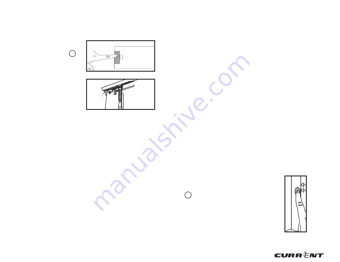
To place the SMART WAND

 into Programming 

Mode, press and hold the PROGRAMMING BUTTON    
b  until you hear a DOUBLE BEEP(2),  then release 
[Fig. 16]. 

Prior to hearing a DOUBLE BEEP (2), you will hear 
a SINGLE BEEP (1), then a DOUBLE BEEP (2). 
After hearing THE DOUBLE BEEP (2), release. The 
SMART WAND™  is now in Programming Mode.

PROGRAMMING SLAT POSITIONS

NOTE

: Be careful to not sum up the number of beeps you have heard, 

for example, a SINGLE BEEP (1) and then a DOUBLE BEEP (2) is not a 
TRIPLE BEEP (3).

Figure 16, Press and Hold 

Programming Button

For further assistance during programming, please view our online 

instructional videos.

Reattach Adjacent Vertical Slat.

You have now completed installing your SMART WAND™. You may 

now proceed to Programming the SMART WAND™ [Pg. 13].

During the programming phase, if an error is made, the SMART 
WAND

 will play a short tune. his means that you must restart the 

programming steps for that SMART WAND

1. Placing the SMART WAND into Programming 

Mode

Содержание Smart Wand

Страница 1: ...l 561 961 5585 Fax 561 961 5587 Certification Exhibit FCC ID 2AJXXCP16E0060 IC 22151 CP16E0060 FCC Rule Part 15 231 ISED Canada Radio Standards Specification RSS 210 ACS Project 16 2062 Manufacturer Current Products Corp Model CP16E0060 User Manual ...

Страница 2: ...1 User Guide and Installation Manual SMART WAND ...

Страница 3: ...ist Group 17 Making Sense of the Sensors 18 Sensor Positions 18 Sensor Features 18 Optional Steps 19 Removing Your SMART WAND from a Group 19 Master Reset 19 Changing Batteries 20 Attaching a SMART WAND Extension Handle 20 Converting a Corded Tilt Blind 21 Quick User Guide 24 Operation of a Single SMART WAND 24 Controlling a Group of Blinds 24 Light Sensor Automation 24 Temperature Sensor Automati...

Страница 4: ...maintaining acomfortable roomtemperature and help you save energy Lastly the SMART WAND requires six 6 1 5v Alkaline AA sized batteries provided which are easy to replace and will provide in most cases multiple years between battery changes Congratulations on your recent purchase of the SMART WAND TWIST HANDLE f BATTERY CAP g VERTICAL BLIND REINFORCEMENT TAPE E HORIZONTAL BLIND MOUNT B VERTICAL BL...

Страница 5: ...ly Right Blind Slats Vertical Fully Open Blind Slats Horizontal Fully Open Blind Slats Vertical Fully Up Blind Slats Horizontal Fully Left Blind Slats Vertical NOTE Some blinds use a corded tilt mechanism to tilt the slats instead of a wand If your blinds have a corded tilt mechanism you will need to convert it to a wand tilt mechanism using the provided horizontal tilt gear Instruactions for conv...

Страница 6: ...al or fully opened positon and the header is free of dirt grime and grease If not use a household cleaner to clean the header before installation Detach the original manual tilt wand and attach the SMART WAND to the blind s wand hook Mount your SMART WAND A Fig 3 by connecting or inserting the SMART WAND S slat ATTACHMENT HOOK a to your blind s tilt gear stem Carefully push up the plastic RETAININ...

Страница 7: ...cal blind mount Figure 11 Detach Slat Install the VERTICAL BLIND MOUNT C onto the SMART WAND Install the VERTICAL BLIND MOUNT C on the SMART WAND by sliding the clear plastic bellows over the ATTACHMENT HOOK a until it fits snuggly on the SMART WAND frame Fig 12 Figure 12 Attach Vertical Blind Mount Attach the SMART WAND to the Vertical Blind Pull down on the VERTICAL BLIND MOUNT S C bellowstoexpo...

Страница 8: ...D into Programming Mode press and hold the PROGRAMMING BUTTON b until you hear a DOUBLE BEEP 2 then release Fig 16 Prior to hearing a DOUBLE BEEP 2 you will hear a SINGLE BEEP 1 then a DOUBLE BEEP 2 After hearing THE DOUBLE BEEP 2 release The SMART WAND is now in Programming Mode PROGRAMMING SLAT POSITIONS NOTE Be careful to not sum up the number of beeps you have heard for example a SINGLE BEEP 1...

Страница 9: ...ogramming Button Figure 17 2 Fully Down Blind Slats Horizontal Figure 17 3 Fully Right Blind Slats Vertical 2 SETTING THE 2ND POSITION FULL OPEN TwisttheSMARTWAND TWISTHANDLE f Fig 18 in the OPPOSITE direction than the first phase of programming to move slats of the shade to the FULL OPEN position Fig 18 2 or 18 3 then release the TWIST HANDLE f Press and hold the PROGRAMMING BUTTON b You will hea...

Страница 10: ... and programming We recommend linking SMART WAND s prior to installation on challenging to reach windows CREATING A TWIST GROUP OPTIONAL PROGRAMMING This SMART WAND feature allows you to group multiple SMART WAND s together so each will respond to the manual twist movement given to any other SMART WAND s you have placed in the group Figure 21 Push and Hold Programming Button On all of the SMART WA...

Страница 11: ...BUTTON b on the SMART WAND you wish to remove from the group until you hear a SINGLE BEEP 1 Repeat this step to remove additional SMART WAND s from the group MASTER RESET YOUR SMART WAND Master reset is performed to return a SMART WAND to its factory default settings All twist groups paired remotes and positional settings will be removed from the memory of the SMART WAND Press and hold the PROGRAM...

Страница 12: ...d tilt gear assembly is shown in Fig 25 Remove the tassels by either cutting the cord or removing the knots at the end of the cord Fig 26 Typically the tilt gear is removed by sliding the rod out of the tilt gear slightly bending the header andliftingthetiltgearout Fig 32 Sometimes the rods are retained in place through either a rod pin crimps or the end brackets While each manufacturer installs t...

Страница 13: ...ure 28 Snap in Attachment Place the gear s stem through the opening in the header and slide the rod through the gear to its original position Fig If a rod pin or the end brackets were removed while removing the corded tilt gear replace back into their original position Figure 29 Slide gear stem through header You are now ready to reinstall your blinds and install the SMART WAND Please proceed to t...

Страница 14: ... the TWIST HANDLE to the position where you would like the single blind to remain LIGHT SENSOR AUTOMATION The SMART WAND has an internal light sensor providing the capability to automatically close your slats at night to provide full privacy in the room and open your slats in the morning to allow in natural light The LIGHT SENSOR SWITCH d allows the user to control the light sensor and has three p...

Страница 15: ...the toggle button until the slats get to the desired position then release the toggle FULL UP LEFT Moves the slats to the full up position for horizontal blinds or full right position for vertical blinds FULL OPEN Moves all slats to the full open position FULL DOWN RIGHT Moves all slats to the full down position for horizontal blinds or full left position for vertical blinds FAVORITE The user can ...

Страница 16: ...leted the process If you ever need to unpair you can repeat the same steps and press the bottom button on the tilt toggle to unpair Fig 33 1 1 4 3 2 5 CH Figure 33 Push To Pair 1 4 3 2 5 CH Figure 33 1 Push to Unpair PAIRING THE REMOTE SETTING THE FAVORITE BUTTON The FAVORITE Button allows the user to program a slat position unique to the user which moves all slats included on that channel to the ...

Страница 17: ...mits for a Class B digital device pursuant to Part 15 of the FCC Rules These limits are designed to provide reasonable protection against harmful interference in a residential installation This equipment generates uses and can radiate radio frequency energy and if not installed and used in accordance with the instructions may cause harmful interference to radio communications However there is no g...

Страница 18: ...r de l appareil doit accepter tour brouillage radioélectrique subi même si le brouillage est susceptible d en compromettre le fonctionnement This equipment complies with the radiation exposure limits in an uncontrolled environment This equipment is in direct contact with the user s body under certain operating conditions This transmitter must not be co located or operating in conjunction with any ...

Страница 19: ...used for other than the customary usage or for other than the Product s intended use v the Product has been subject to mishandling misuse or abuse vi the product has suffered damage resulting from lightning power surges vandalism fire earthquake acts of nature or any other cause which the product was not designed to withstand or vii damage to the Product cause by battery decay or corrosion This Li...

Страница 20: ...36 Current Products Corp 1995 Hollywood Ave Pensacola FL 32505 www currentproductscorp com 850 435 4994 ...

Отзывы: