background image

4

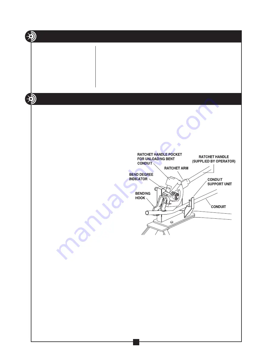
Figure 1

SPECIFICATIONS

  Model No.   


750

  Capacity   


½

" to 1" RIGID and IMC conduit and 


schedule 40 pipe

 
  Overall Dimensions 

48" L x 24 

½

" W x 30" H

  Weight 


91 lbs.

OPERATING INSTRUCTIONS

1.  Cut a 5' length of 1" RIGID conduit and insert it into the ratchet arm as  

    shown in Figure 1. This will serve as the ratchet handle.
2.  Place the ratchet handle in the up position. This will release the ratchet pawl.  

    Rotate the bending shoe counter-clockwise. Then lower the ratchet handle.

3.  Slide the conduit to be bent  

    over the corresponding size  

    on the conduit support unit,  

    through the shoe groove and  

    bending hook.
4.  Place the bending mark on the  

    conduit in line with the front  

    edge of the bending hook.  

    See Figure C on page 6.
5.  Raise the ratchet handle until  

    the pawl clicks. Push the ratchet  

    handle down. Repeat until you  

    have completed the desired bend.

6.  To remove bent conduit, raise the ratchet handle to the up position.  

    Remove the ratchet handle from the ratchet arm and slide it into the pocket 

    provided on the bending shoe. While holding the bent conduit, slowly  

    rotate the bending shoe in the counter-clockwise direction and remove  

    the bent conduit. 
7.  Place the ratchet handle back into the ratchet arm and lower the ratchet  

    handle to the down position.
    NOTE: 

Springback compensation is not calculated on the 

    bending degree indicator.

    NOTE: 

When not in use the ratchet handle MUST remain in 

    the down position.

Содержание 750 Tweaker

Страница 1: ...Maintenance Safety and Parts Manual This manual is free of charge All personnel who operate the Mechanical Bender should have a copy of this manual and read and understand its contents To request a copy call or write to the address below Read and understand this material before operating or servicing the Mechanical Bender Failure to understand how to safely operate and service this unit could resu...

Страница 2: ... to call your attention to instructions that concern your personal safety It means ATTENTION BE AWARE THIS IS AN IMPORTANT SAFETY INSTRUCTION Read understand and follow these safety instructions Failure to follow these safety instructions may result in injury or death Safety Alert Symbol 2 TABLE OF CONTENTS Safety Alerts 2 Safety Information 3 Specifications 4 Operating Instructions 4 The TWEAKER ...

Страница 3: ...lined surface ALWAYS keep the path of the bending conduit clear of obstructions Keep firm hand pressure on the ratchet handle while bending The stored energy of bending conduit could cause the ratchet handle to spring forward and strike operator or nearby personnel REMOVE the ratchet handle and conduit before moving the bender Keep firm control of the bender T handle when moving the bender to avoi...

Страница 4: ...ace the bending mark on the conduit in line with the front edge of the bending hook See Figure C on page 6 5 Raise the ratchet handle until the pawl clicks Push the ratchet handle down Repeat until you have completed the desired bend 6 To remove bent conduit raise the ratchet handle to the up position Remove the ratchet handle from the ratchet arm and slide it into the pocket provided on the bendi...

Страница 5: ...it or schedule 40 pipe To use the TWEAKER 1 Insert the conduit between the TWEAKER shafts shown on Figure 2 2 Apply pressure to conduit as needed to correct overbend MAINTENANCE Monthly Apply multi purpose grease at grease fitting See Item 27 on Exploded View on Page 8 Monthly Apply a few drops of oil into oil hole on bending shoe See Item 1 on Exploded View on Page 8 ...

Страница 6: ...or stubs 1 Check the Stub Dimensions Chart below for Minimum Stub Length The stub being bent must be equal to or longer than the Minimum Stub Length 2 Measure and mark the stub length required on the conduit This is the stub length mark See Figure A Locate the Deduct Length on the Stub Dimensions Chart below Deduct this length from the stub length mark and make a second mark This is the bending ma...

Страница 7: ...nd 1 4 on 45 bends Deduct Chart Conduit Deduct Size Length 2 3 1 4 Figures are approximate OFFSET BENDING INFORMATION To mark conduit for offsets 1 Measure distance from end of conduit to start of first bend and mark conduit This is mark 1 See Figure 1 and 2 2 Refer to Deduct Chart and deduct this length from mark 1 and place mark 2 on conduit See Figure 1 3 Measure the height of the obstacle This...

Страница 8: ...8 EXPLODED VIEW Model 750 Mechanical Bender 14 29 13 3 27 25 26 24 2 23 11 10 6 15 21 22 OIL HOLE 4 20 1 17 12 16 19 5 7 8 18 9 33 ...

Страница 9: ...09 13 2 WHEEL 14 77 016 2 COTTER PIN 15 750 348 1 BENDING DEGREE INDICATOR 16 750 18 2 7 8 9 HEX LOCK NUTS THIN 17 750 382 1 INDICATOR ARROW 18 750 20 1 20 X HEX HD SCREW 19 750 21 2 RETAINING RING 20 750 22 1 RETAINING RING 1 21 750 394 1 WASHER 22 750 25 3 3 8 16 X 1 HEX HD SCREW 23 452 27 3 3 8 LOCK WASHER 24 281 2C 4 LOCK WASHER 25 281 1F 4 13 X 1 HEX CAP SCREW 26 280 2G 4 13 HEX NUT 27 88 39 ...

Отзывы: