


5) Turn the feedwater tapping valve handle clockwise to close
the valve. With a wrench, tighten the nut/seal around the
valve handle stem.
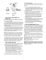
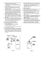
6) Remove the cover from the appliance and disconnect the
orange 1/4" tubing from the feedwater fitting. (See Fig. 6)
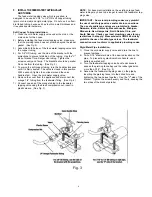
7) Connect one end of the orange tubing to the feedwater
tapping valve using the brass compression nut, insert, and
plastic sleeve. (See Fig. 3)
NOTE:
For basement installations, the existing orange feed-
water tubing may have to be longer to reach the feedwater tap-
ping valve.
G. PREFILL AND SANITIZE THE STORAGE TANK
Prefilling the storage tank is always recommended so that
there is pressure to check for leaks as well as sufficient water
to flush the carbon postfilter. The SQC RO Drinking Water
Appliance is furnished with a container of special sanitizing
granules. It is important to use a sanitizer when prefilling the
tank.
1) Thread the taped 3/8" x 1/4" tank fitting into the tank valve.
Do not over tighten. Open the tank valve so that the tank
handle is parallel to the valve body. Locate the enclosed
container of sanitizing granules, open it and pour the
contents into the end of the tank valve.
2)
Disconnect the 3/8" yellow tubing from the back of the
purification assembly and connect one end of it into the tube
fitting located on the tank valve.
3) Connect the other end of the 3/8" yellow tubing to the 3/8"
x 1/4" union connector included in the tank sanitization kit.
4) Connect the free end of the 1/4" orange feed water tubing
to the other end of the 3/8" x 1/4" union connector.
5)
Open the feedwater tapping valve (making sure the tank
valve is still open) and allow the tank to fill (about 3 minutes).
6) Close the feedwater tapping valve and the tank valve.
Disconnect the 3/8" yellow tubing from the tank valve
elbow fitting and set the tank aside while proceeding with
the rest of the installation (the sanitizing solution should be
kept in the tank for at least 15 minutes).
NOTE:
If you encounter difficulty in removing the tubing from
the tank, make sure the tank valve is closed and then cut the
yellow tubing approximately 1" away from the tank valve fitting to
relieve the pressure. Remove the 1" piece from the tank fitting.
NOTE:
If an alternate storage tank is used, it should be sani-
tized with household bleach (5-1/4%). Use 3 ml. (1/2 tea-
spoon) of bleach for a 2.5 gallon tank.
7) Reconnect the 3/8" yellow tubing to the back of the
purification assembly. Reconnect the 1/4" orange tubing to
the feedwater fitting on the purification assembly.
IMPORTANT:
After the installation is complete, it is recom-
mended that the 3/8" x 1/4" union connector be saved for
future use in tank sanitization.
H. INSTALL THE DRAIN CONNECTION
IMPORTANT:
Before starting this procedure, inspect the con-
dition of the drain piping, especially in older homes where the
traps and tailpieces can be deceptively thin and frail. If they
are in poor condition, it is wise to inform the customer that the
condition should be remedied.
IMPORTANT: Some local plumbing codes may prohibit
the use of saddle-type valves and/or drain connections.
The use of saddle-type valves are prohibited in Alaska,
Delaware, Idaho, Kentucky, Massachusetts, Michigan,
Minnesota, New Hampshire, North Dakota, Ohio, and
South Dakota. Check your local plumbing codes for any
restrictions that apply. Massachusetts CMR 248 strictly
prohibits the use of saddle-type valves. The feedwater
connection must conform to applicable plumbing codes.
Undercounter Installation:
The drain saddle assembly is designed to fit around a
standard 1-1/2" OD drain pipe. For smaller (lavatory type) or
larger (ABS pipe) drains, consult your dealer for special drain
saddles.
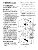
The drain saddle should always be installed above (before)
the trap and on the vertical or horizontal tailpiece. Never install
the drain saddle close to the outlet of a garbage disposal
because plugging of the RO drain line may occur. (See Fig. 4)
1)
Position the threaded half of the drain saddle at the selected
location and mark the pipe through the threaded opening.
2)
Drill a 1/4" hole at the marked location through one side of
the drain tailpiece.
3)
Position both halves of the drain saddle on the drain pipe
so that the threaded opening is lined up with the hole in
the drain pipe.
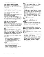
4)
Use the screws and nuts to clamp the drain saddle onto
the drain pipe. Make sure that there is equal space
between saddle halves on each side. Do not overtighten.
(See Fig. 5)
5)
Orient the elbow in the direction of the RO faucet location.
Fig. 4
7
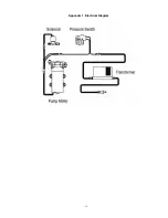
Содержание SQC Pro
Страница 15: ...Appendix 1 Electrical Diagram 15 ...


