background image


15


5.  Place the printer upside down and unscrew the two screws of the 

hinge holder

 on 

the lower cover. 

6.  Unscrew the screw of the memory card cover and remove the memory card cover. 

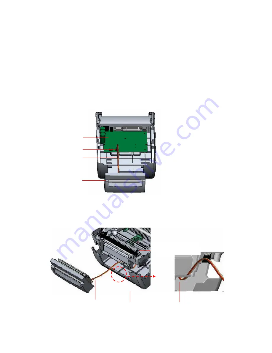
Plug in the cutter driver IC at U30 socket on the main board.

7.  Use both thumbs to hold the lower cover and index fingers to lift up the top cover 

open levers to separate the lower inner cover and the lower cover. 

8.  Arrange the cable through the bezel. Connect the cutter module cable to the 4-pin 

socket on printer PCB. 


Fig. 24 Cutter module installation 


Fig. 25 Cutter module cable arrangement 


PCB 

4-pin Socket 

Cutter Cable 


Cutter


Lower Inner Cover


Lower Cover


Cutter Cable


Bezel 

Содержание CB-534e

Страница 1: ...USER S MANUAL Cub CB 724e CB 534e THERMAL TRANSFER DIRECT THERMAL BAR CODE PRINTER ...

Страница 2: ...ode 16 3 7 Instructions to Top Cover Operation 17 3 8 Diagnostic Tool 20 3 8 1 Start the Diagnostic Tool 20 3 8 2 Printer Function Calibrate sensor Ethernet setup RTC setup 21 3 9 Install Memory Card 22 4 Power on Utilities 24 4 1 Ribbon and Gap Black Mark Sensor Calibration 24 4 2 Gap Black Mark Calibration Self test Dump Mode 25 4 3 Printer Initialization 28 4 4 Black Mark Sensor Calibration 29 ...

Страница 3: ...map fonts and built in true type font capabilityareincluded CAUTION 1 HAZARDOUS MOVING PARTS IN CUTTER MODULE KEEP FINGERS AND OTHER BODY PARTS AWAY 2 THE MAIN BOARD INCLUDES REAL TIME CLOCK FEATURE WHICH HAS A LITHIUM BATTERY INSTALLED RISK OF EXPLOSION IF BATTERY IS REPLACED BY AN INCORRECT TYPE 3 DISPOSE OF USED BATTERIES ACCORDING TO THE MANUFACTURER INSTRUCTIONS 2 Getting Started 2 1 Unpackin...

Страница 4: ...hased reseller or distributor Dealer option Peel off module assembly Guillotine cutter Full cut Paper thickness 0 06 0 19mm 500 000 cuts Partial cut Paper thickness 0 06 0 12mm 500 000 cuts Paper thickness 0 19mm 200 000 cuts Main board integrated with internal Ethernet Internal Ethernet print server module ...

Страница 5: ...ower switch is off 3 Connect the printer to the computer with the Centronics Serial or USB cable 4 Plug the power cord into the power supply connector at the rear of the printer and then plug the power cord into a properly grounded receptacle Top Cover Open Lever LED Indicator Feed Button Printer Top Cover Ribbon Access Cover Clear Window ...

Страница 6: ...follow the steps below to install the ribbon into printer 1 Push down on the ribbon access window to unlatch and open the cover 2 Place a paper core onto the ribbon rewind spindle 3 Mount the ribbon rewind paper core on the front hubs 4 Install a ribbon on the ribbon supply spindle 5 Mount the ribbon supply spindle on the rear hubs 6 Thread the ribbon leading tape downward pass the print head 7 At...

Страница 7: ... I Fig 5 Ribbon installation II 3 3 Loading Label Stock 1 Insert the 1 label spindle into the label roll If your label roll has a 1 core remove the 1 5 core adapter from the fixed tab If label width is 4 inches wide the two fixing tabs Ribbon Spindle Front Hub Paper Core Back Hub Ribbon Access Cover Rear Hub ...

Страница 8: ...l roll onto the center of the paper roll mount 4 Feed the label printing side face up under the Teflon bar and paper guides and pass over the platen 5 Adjust the green center biased paper guides to slightly touch the edges of the label backing 6 To close the printer top cover lift the cover to the maximum open angle then use both hands to close the cover gently Close the printer top cover slowly a...

Страница 9: ...ach an external paper roll mount on the bottom of the printer Fig 9 Attach the external roll mount to the printer 1 Open the printer top cover by releasing the top cover open levers The top cover support will hold the printer top cover 2 Install a roll of 3 core labels on the external roll mount using the 3 core adapter 3 Feed the label to the external paper feed opening through the rear paper gui...

Страница 10: ...platen 5 Adjust the paper guides to fit the paper width 6 Close the printer top cover by lifting the top cover to the maximum opening angle then push down the top cover gently Fig 11 External roll mount label installation II External Paper Feed Opening External Paper Roll Mount Paper Guide Platen Rear Paper Guide Top Cover Support ...

Страница 11: ... and push down and push backward the top cover support then push backward the top cover 3 Use a screwdriver to screw off 6 screws on the lower inner cover Fig 13 Remove 6 screws from lower inner cover 4 Upside down the printer Remove two screws at the hinge and remove one screw at Front Panel Lower Cover Screws Lower Inner Cover Top Cover Screws Top Cover Support Flute ...

Страница 12: ... inner cover and the lower cover 6 Arrange the cable through the bezel Connect the peel off panel cable to the 5 pin socket on printer PCB Fig 14 Connect peel off sensor cable to main board Fig 15 Peel off sensor cable installation Peel off panel Peel off panel Cable 5 pin Socket PCB Tenon Bezel Mortise ...

Страница 13: ... Fig 17 Peel off panel installation II 9 Lift up the peel off panel to the lower cover to close it 10 Use a screwdriver to screw down whole screws on the lower inner cover and the lower cover 11 Close the top cover by arranging the top cover support back to the flute and push it forward then close the top cover slowly Roller Tenon Mortise Lower Inner Cover Lower Cover Peel off panel Roller ...

Страница 14: ...nsert a 1 label spindle into a paper roll 2 Open the printer top cover by pulling the top cover open levers The top cover support will hold the printer top cover Fig 18 Open the top cover 3 Install the label roll on the label roll mount 4 Open the peel off panel by pulling it out Fig 19 Open the peel off panel Peel off panel Top Cover Open Lever Peel off panel Backing paper Opening ...

Страница 15: ... right to fit the paper width Fig 20 Lead the paper through the backing paper opening beneath the roller 8 Push the peel off panel back to the printer 9 Close the top cover by lifting up the top cover support and close the top cover slowly Note Pull the label outward tightly after closing the top cover Fig 21 Complete label installation for peel off mode Roller Top Cover Top Cover Support Peel off...

Страница 16: ... lever to open the cover 3 Open the top cover and hold it and push down and push backward the top cover support then push backward the top cover 4 Use a screwdriver to screw off 6 screws on the lower inner cover Fig 23 Remove 6 screws from lower inner cover Lower Cover Screws Top Cover Screws Top Cover Support Flute Lower Cover Lower Inner Cover Front Panel ...

Страница 17: ...he main board 7 Use both thumbs to hold the lower cover and index fingers to lift up the top cover open levers to separate the lower inner cover and the lower cover 8 Arrange the cable through the bezel Connect the cutter module cable to the 4 pin socket on printer PCB Fig 24 Cutter module installation Fig 25 Cutter module cable arrangement PCB 4 pin Socket Cutter Cable Cutter Lower Inner Cover Lo...

Страница 18: ...g the top cover support back to the flute and push it forward then close the top cover slowly 3 6 1 Loading Label in Cutter Mode 1 Insert a 1 label spindle into a label roll 2 Open the printer top 3 Install the label roll onto the label roll mount 4 Feed the paper printing side face up through the paper guide and pass over the platen 5 Lead the paper through the cutter label opening 6 Adjust the p...

Страница 19: ... installation in cutter mode 3 7 Top Cover Operation Please take care when opening or closing the printer s top cover by carefully following these instructions To Open 1 When facing the front of the printer pull the cover release levers on both sides of printer towards you 2 Lift up the top gradually Top Cover Top Cover Support Paper Guide Platen Cutter ...

Страница 20: ...e top cover and gently lower it to stop position 2 Fig 1 Top cover support is fixed at position 2 4 To close the cover lift up the top cover to the maximum angle then close the top cover gently The cover will rest at a stop position between 1 and 2 for a while Use both hands to gently push down the top cover to close it Make sure the cover is latched on both sides Note Do not place your hands betw...

Страница 21: ...over If you are not sure if the top cover is at the stop position please do not push the top cover to close it or the top cover will be damaged Please open the top cover to the maximum angle to close the top cover again Use both hands to push the top cover to close it ...

Страница 22: ...is convenient tool you can explore the printer status settings and troubleshoot the printer The Diagnostic tool can be found on the provided CD in the utilities folder Note This utility works with printer firmware V6 00 and later versions 3 8 1 Start the Diagnostic Tool 1 Double click on the Diagnostic tool icon to start the software 2 There are four feature tabs Printer Configuration File Manager...

Страница 23: ...ault Dump Text To activate the printer dump mode Configuration Page Print printer configuration RTC Setup Synchronize printer Real Time Clock with PC Calibrate Sensor Calibrate the sensor specified in the Printer Setup group media sensor field Reset Printer Reboot the printer Print Test Page Print a test page Ignore AUTO BAS Ignore the downloaded AUTO BAS program Ethernet Setup Setup the IP addres...

Страница 24: ... card specification SD card spec SD card capacity Approved SD card manufacturer V1 0 V1 1 128 MB SanDisk Transcend V1 0 V1 1 256 MB SanDisk Transcend Panasonic V1 0 V1 1 512 MB SanDisk Transcend Panasonic V1 0 V1 1 1 GB SanDisk Transcend Panasonic V2 0 SDHC CLASS 4 4 GB V2 0 SDHC CLASS 6 4 GB SanDisk Transcend Panasonic V1 0 V1 1 microSD 128 MB Transcend Panasonic V1 0 V1 1 microSD 256 MB Transcen...

Страница 25: ...1 1 miniSD 256 MB Transcend Panasonic V1 0 V1 1 miniSD 512 MB Transcend Panasonic V1 0 V1 1 miniSD 1 GB Transcend Panasonic V2 0 SDHC CLASS 4 miniSD 4 GB Transcend V2 0 SDHC CLASS 6 miniSD 4 GB The DOS FAT file system is supported for the SD card Folders files stored in the SD card should be in the 8 3 filename format The miniSD microSD card to SD card slot adapter is required ...

Страница 26: ... calibrated under the following conditions 1 Installing a brand new printer 2 Change label stock 3 Printer initialization Please follow the steps below to calibrate the ribbon and gap black mark media sensor 1 Turn off the power switch 2 Press down and hold the feed button while turning on the printer s power switch 3 Release the feed button when LED begins blinking red The printer will blink red ...

Страница 27: ... the printer s power switch 3 Release the feed button when LED begins blinking amber The printer will blink amber 5 times The LED color will change in the following order Amber Æ red 5 blinks Æ amber 5 blinks Æ green 5 blinks Æ green amber 5 blinks Æ red amber 5 blinks Æ solid green 4 The printers will calibrate the media sensor and measure the label length The printer will also print the internal...

Страница 28: ...ter element the printers current configuration and available memory space Self test printout Print head check pattern Model name and F W version Printed mileage meter Firmware checksum Serial port configuration Code page Country code Print speed inch sec Print darkness Label size inch Gap distance inch Gap black mark sensor sensitivity Numbers of download files Total available memory space ...

Страница 29: ...ng The left side characters are received from your system The right sides data is the corresponding hexadecimal value of the characters It allows users or engineers to verify and debug programing Fig 30 Dump mode printout Note Cycle the printers power to resume normal printer operation ASCII Data Hex decimal data related to left column of ASCII data ...

Страница 30: ...5 blinks Æ green amber 5 blinks Æ red amber 5 blinks Æ solid green Printer configuration will be restore to defaults as below after initialization Parameter Default setting Speed CB 724e Series 127 mm sec 5 ips CB 534e Series 76 mm sec 3 ips Density 8 Label Width 4 101 6 mm Label Height 4 101 6 mm Sensor Type Gap sensor Gap Setting 0 12 3 0 mm Print Direction 0 Reference Point 0 0 upper left corne...

Страница 31: ...off the power switch 2 Press down and hold the feed button while turning on the printer s power switch 3 Release the feed button when LED begins blinking red amber The printer will blink red amber 5 times The LED color will be changed as following Amber Æ red 5 blinks Æ amber 5 blinks Æ green 5 blinks Æ green amber 5 blinks Æ red amber 5 blinks Æ solid green 4 6 Skip AUTO BAS TSPL2 programming lan...

Страница 32: ...D button when the LED becomes solid green The LED color will be changed as following pattern Orange Æ red 5 blinks Æ orange 5 blinks Æ green 5 blinks Æ solid green 4 Printer will be interrupted to run the AUTO BAS program ...

Страница 33: ... Allow the print head to cool for a minimum of one minute 3 Use a cotton swab or Head cleaner pen and 100 ethanol to clean the print head surface Clean the print head when changing a new ribbon roll Print Head Platen Roller 1 Turn the power off 2 Rotate the platen roller and wipe it thoroughly with 100 ethanol and a cotton swab or lint free cloth Clean the platen roller when changing a new ribbon ...

Страница 34: ...ead by hand If you touch it please use ethanol to clean it z Please use 100 Ethenol DO NOT use medical alcohol which may damage the printer head z Regularly clean the print head and sensors when changing a new ribbon This will keep printer performance and extend the printers life ...

Страница 35: ...lit on power supply If it is not lit on power supply is broken Check both power connections from the power cord to the power supply and from the power supply to the printer power jack if they are connected securely Solid Green ON The printer is ready to use No action necessary Green with blinking Pause The printer is paused Press the FEED button to resume for printing Red with blinking Error The l...

Страница 36: ...ibbon not loaded correctly Follow the instructions to load the media or ribbon No print on the label Ribbon ran out Load a new ribbon Continuous feeding labels The printer media setting is not correct Run the initialization and gap black mark media calibration Gap black mark sensor sensitivity is not set properly sensor sensitivity to low Calibrate the gap black mark sensor Make sure label size is...

Страница 37: ...nsity is set properly Adjust the print density and print speed Check print head test pattern if head element is damaged Run printer self test and check the print head test pattern to see if dots are missing in the pattern ...

Страница 38: ...ss the button when the LED is green Printer advances to the beginning of the next label Pause z Press the feed button during printing Printer pauses the print job Ribbon Sensor and Gap Black Mark Sensor Calibration 1 Turn off the power switch 2 Hold the feed button while turning on the power switch 3 Release the button when LED begins blinking red The printer will blink red 5 times Printer will ca...

Страница 39: ...ensor calibration Printer Initialization 1 Turn off the power switch 2 Hold on the button then turn on the power switch 3 Release the button when LED turns green after 5 amber blinks Any green will do during the 5 blinks The LED color will be changed as following Amber Æ red 5 blinks Æ amber 5 blinks Æ green 5 blinks Æ green amber 5 blinks Æ red amber 5 blinks Æ solid green Note Always do gap blac...

Страница 40: ...mber Æ red 5 blinks Æ amber 5 blinks Æ green 5 blinks Æ green amber 5 blinks Æ red amber 5 blinks Æ solid green Skip AUTO BAS 1 Turn off printer power 2 Press the FEED button and then turn on power 3 Release the FEED button when LED becomes solid green The LED color will be changed as following Amber Æ red 5 blinks Æ amber 5 blinks Æ green 5 blinks Æ green amber 5 blinks Æ red amber 5 blinks Æ sol...

Страница 41: ......

Отзывы: