


12
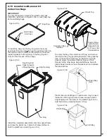
2-9 Lower Mount Tube Installation
Secure the (2) lower mount tubes P#(B0640) to the
lower main frame using (2) 5/16”-18 u-bolts P#(K1098)
and (4) 5/16”-18 nylon flange locknuts P#(K2516) PER
TUBE. Refer to Figure 2-10.
2-10 Upper Frame Assembly
Installation
Position the upper frame assembly P#(A1058) above the
lower mount tubes as shown in Figure 2-10. Slide the
upper frame assembly down onto the lower mount tubes
and secure using (2) clevis pins P#(K0133) and (2) hair
pin clips P#(K0088).
Figure 2-10
Upper Frame
Assembly
Lower
Mount Tube
Lower
Main Frame
(2) 5/16”-18
U-Bolts
PER TUBE
(4) 5/16”-18
Locknuts
PER TUBE
Lower
Mount Tube
Clevis
Pin
Hair Pin
Clip
Clevis
Pin
Содержание 21131508
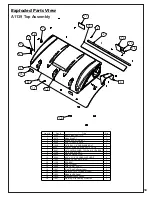
Страница 20: ...20 A1841_01 PTO Arm Assembly ...
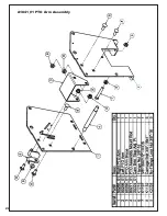
Страница 21: ...21 A1941_01 PTO Base Assembly Exploded Parts View ...
Страница 22: ...22 A1941_01 PTO Base Assembly Exploded Parts List ...
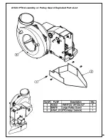
Страница 23: ...23 A1623 PTO Assembly w Pulley Guard Exploded Parts List ...
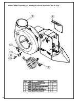
Страница 24: ...24 A1821 PTO Assembly w Safety Interlock Exploded Parts List ...
Страница 25: ...25 ...
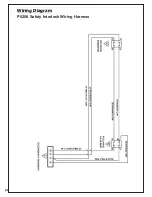
Страница 26: ...26 Wiring Diagram P0208 Safety Interlock Wiring Harness ...
Страница 30: ...30 ...
Страница 31: ...31 NOTES ...