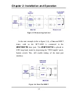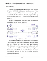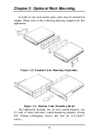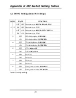
Chapter 2: Installation and Operation
13
2.6 Front Panel
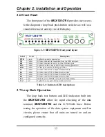
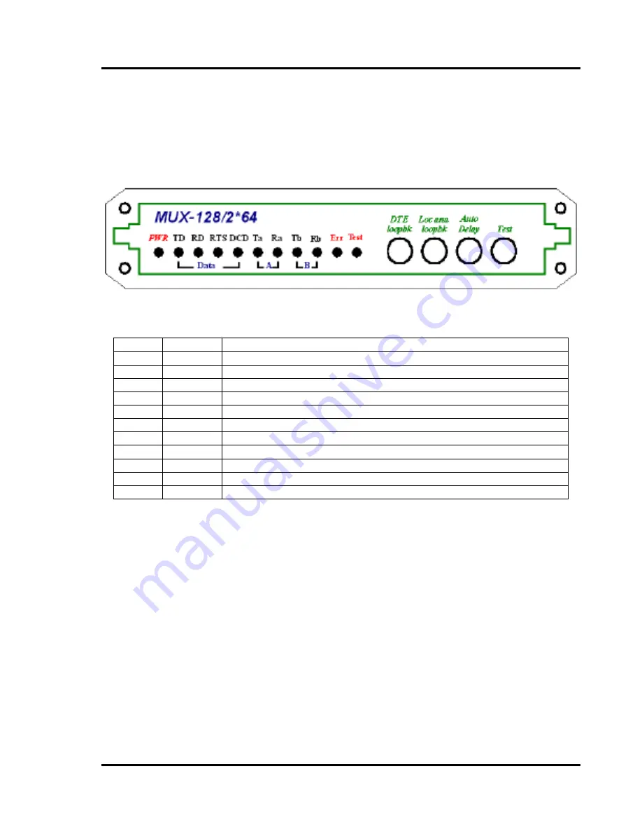
The front panel of the
MUX128/2*64
provides user access
to the diagnostic loop back push-button switches as well as a
visual reference of activity via LED display.
Figure 2-3:
MUX128/2*64
front panel layout
Label
Color
Description
PWR
green
Lights when unit is powered on.
TD
yellow
Flashes when data is transmitted from the 128K data port.
RD
yellow
Flashes when data is received at the 128K data port.
RTS
yellow
Lights when the connected DTE equipment supplies RTS.
DCD
yellow
Normally, should be lit during operation.
Ta
yellow
Flashes when G.703 A-channel transmits data.
Ra
yellow
Flashes when G.703 A-channel receives data.
Tb
yellow
Flashes when G.703 B-channel transmits data.
Rb
yellow
Flashes when G.703 B-channel receives data.
Err
red
Indicates error in BERT or slip in A-B channel delay.
Test
red
Lights when any push-button switch is selected.
Table 2-1: Indicator LED descriptions
2.7 Loop Back Operation
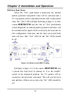
The loop back test buttons and LED indicators built into
the
MUX128/2*64
allow for rapid checking of the data
terminal,
MUX128/2*64
and the G.703/64K lines. Before
testing the operation of the data system equipment and line
circuits, please ensure that all units are turned on and are
configured correctly.
Содержание MUX128
Страница 1: ...INSTALLATION and OPERATIONMANUAL ...
Страница 2: ......
Страница 26: ...Appendix A DIP Switch Setting Tables 22 This page left blank intentionally ...
Страница 34: ......
Страница 35: ......

