

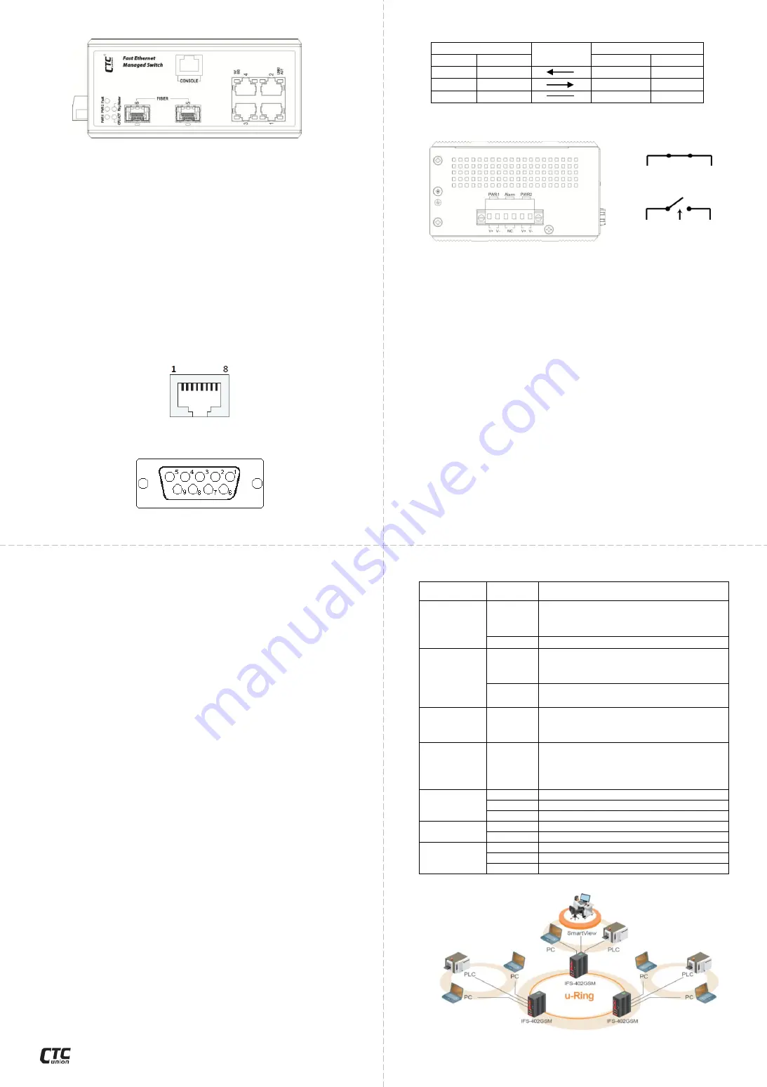
Connectors
LAN & Fiber Ports
IFS-402GSM(-E) switches have 4 electrical LAN ports (labeled
1
~
4) and 2 fiber ports (SFP based, labeled 5
~
6) on the front panel.
The LAN ports that utilize shielded RJ-45 connectors support
10/100M; while the fiber SFP ports support 100/1000M.
CONSOLE Port
The RJ-45 port labeled “CONSOLE” is an RS-232 terminal port
for local management. These models use a “light” CLI (Command
Line Interface) in addition to a user friendly Web interface and
industry standard SNMP. See page 5 for basic CLI and Web
operation.
One RJ-45 to DB-9 cable is provided with this device. CONSOLE
port pinouts (Figure 2) and RS-232 DB-9 (Figure 3) connector are
illustrated below together with RJ-45 to DB-9 signal mapping
information. Use the supplied cable to connect the RJ-45
CONSOLE port to a console PC.
Figure 2. CONSOLE Port Pinout
Figure 3. RS-232 (Female) Pinout
CLI & Web Basic Operation
IFS-402SM(-E) are managed Fast Ethernet switch devices. Initial
configuration (assignment of IP address) may be accomplished via
the RS-232 console and a PC or laptop running terminal emulation
software. Configure the terminal as follows:
115200 speed
8 data bits
no parity
1 stop bit
no flow control
IFS-402SM(-E) switches use a command line interface (CLI)
through the serial port. Once the IP address has been configured,
a web browser can be used to configure the device through a
more easy to use GUI (graphical user interface). Please refer to
the operation manual on the CDROM.
Using the provided console cable, connect the RJ-45 to the
“CONSOLE” port and the DB9 to PC COM port. Apply power to the
switch. At the "Username:" prompt, enter '
admin
' (lower case, no
quotes). Just
press Enter when prompted for password
.
To set the IP address and subnet mask issue this command:
> ip address 1 192.168.0.250/24
(example: sets VID 1 to 192.168.0.250, subnet 255.255.255.0)
NOTE: The factory default IP address is 10.1.1.1 with mask
255.255.255.0
RJ-45 to DB-9 Signal Mapping
DB-9 (Female)
Direction
RJ-45
Signal
Pin
Pin
Signal
RXD
2
3
TXD
TXD
3
6
RXD
GND
5
5
GND
Power and Alarm
A removable terminal block on the top panel provides both
power and alarm connections. Power can be provided through
the dual inputs from separate sources. The alarm relay contact
can be wired into an alarm circuit which senses an alarm
condition when the contact is broken. The alarm relay is normally
closed when there is no alarm condition. The alarm conditions are
user programmable through management to include power, link
faults or other fault conditions. Please note that the alarm relay
contact can only support 1A current at 24VDC. Do not apply
voltage and current that exceed these specifications.
LED Indicators
LED
Color
Definition
PWR1/
PWR2
Green
Power is connected and active at the
PWR1/PWR2 input terminal
connection.
Off
PWR1/PWR2 is not connected.
Fault
Amber
When one or more of the
programmable alarm conditions is
active.
Off
Normal operation without faults.
Alarm conditions are all disabled.
CPU ACT
Green
During normal use, this LED will be lit,
indicating a healthy condition of the
running CPU.
Ring
Master
Yellow
Lit when this unit is the 'master' in a
fiber ring and all units are configured
for u-Ring or ERPS (Ethernet Ring
Protection Switching or G.8032).
LAN
LINK/ACT
Green
Ethernet link is up.
Blinking
Blinking when there is Ethernet traffic.
Off
No Ethernet link.
10/100
Green
The connected LAN speed is 10/100M.
Off
No Ethernet link.
FIBER
LINK/ACT
Green
The fiber SFP link is up.
Blinking
Blinking when there is data traffic.
Off
No fiber link.
Application
- 6 -
Figure 6. u-Ring Topology and Application
Figure 1. Front Panel
- 4 -
Fault
Figure 5. Alarm Relay Circuit
Normally Closed (NC)
Figure 4. Terminal Block
- 3 -
- 5 -
www.ctcu.com


