Chapter 2. Installation
17
2.4.2
Rear
and
Front
panel
connectors
All
Channels
are
fixed
on
the
rear
of
the
Fiber Multiplexer
.
As
a
manufacturer
of
fiber
multiplexers
for
almost
15
years,
our
experience
has
shown
that
in
less
than
1%
of
cases
will
an
operator
ever
use
the
expansion
feature
of
a
modular
multiplexer
which
is
all
E1
or
T1.
This
additional
cost
for
modular
design
is
born
by
the
operator,
increasing
operating
costs.
In
this
age
where
costs
must
be
controlled,
purchasers
should
be
opting
for
a
low
cost
fixed
design
when
available.
Maintenance
personnel
must
take
on
a
new
mind
set
to
not
specify
high
priced
and
useless
features
when
developing
compliance
documents.
Modular
designed
multiplexers,
of
this
capacity,
are
neither
required
or
are
they
financially
viable.
Modular
designs
are
reserved
for
multi
‐
service
multiplexers
supporting
TDM,
Data
and
Voice.
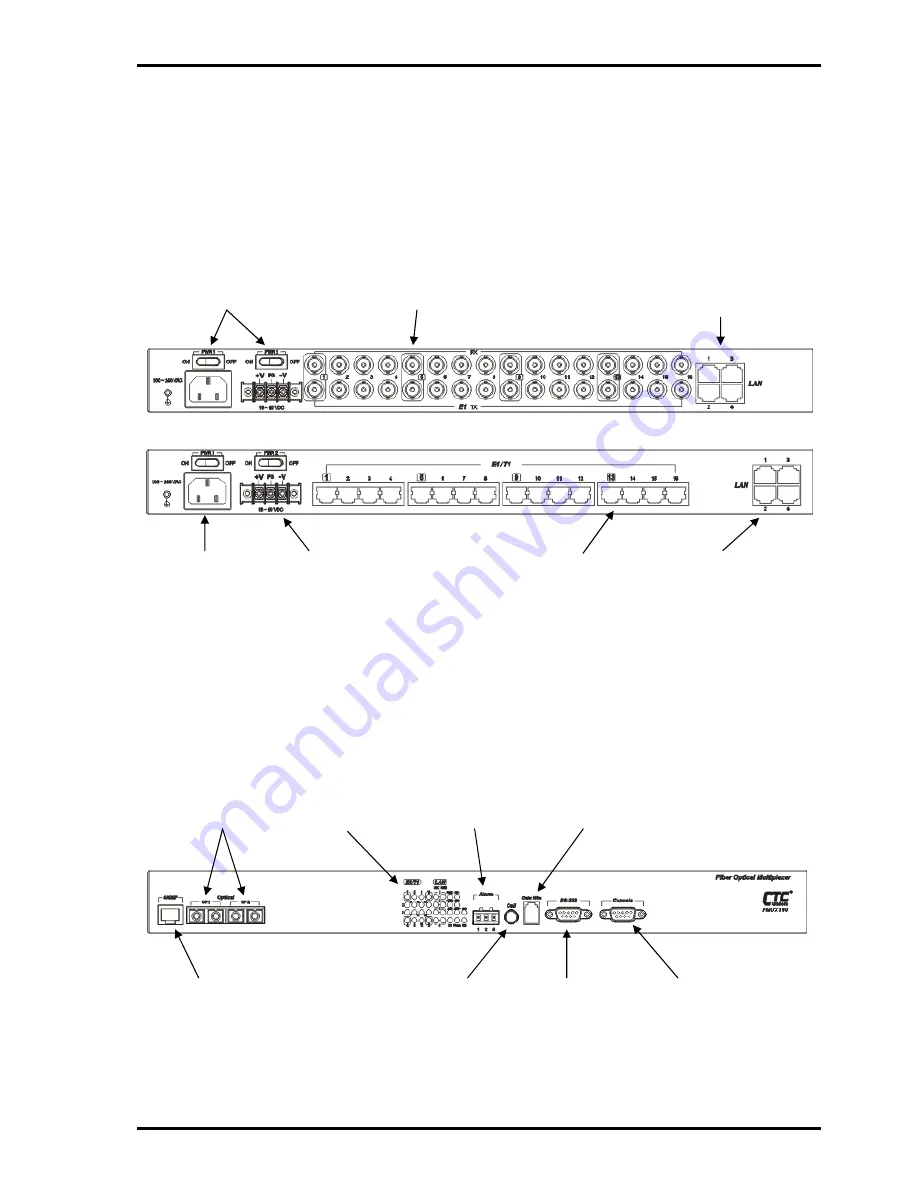
Rear
Panel
(example
FMUX160B)
Rear
Panel
(example
FMUX1600R)
Figure
2
‐
3
:
Rear
Panel
Connections
The
front
panel
of
the
Fiber Multiplexer
,
holds
the
optical
interfaces,
the
status
and
alarm
LEDs,
the
call
button,
order
wire
jack,
clear
RS
‐
232
channel
and
the
local
management
console
port.
The
optical
interfaces
may
be
of
the
Fixed
type
or
pluggable
SFP
type.
The
two
optical
interfaces
provide
1+1
fiber
protection.
The
front
panel
also
provides
the
connections
to
the
RS
‐
232
Console
Interface
(terminal
mode)
and
to
the
management
network
for
SNMP
control
(when
the
SNMP
option
is
installed).
Figure
2
‐
4
:
Front
Panel
Controls
and
Indicators
16
x
E1/T1
balanced
RJ
‐
45
DC
Mains
Terminal
Block
Mains
Switches
AC
Mains
IEC
C14
E1
unbalanced
BNC
Gigabit
Ethernet
Switch
Optical
Interfaces
Alarm
Contacts
RS
‐
232
Clear
Channel
Console
Management
Port
Optical
and
Channel
Status
Indicators
Order
Wire
Fast
Ethernet
Switch
SNMP
Ethernet
Management
Port
Order
Wire
Call
Button
Содержание FMUX160
Страница 2: ......
Страница 34: ...Chapter 3 Operation 34 This page was left blank intentionally ...
Страница 54: ......
Страница 55: ......
Страница 56: ......


