HV Breakout Module – Product Description
Installation Manual
7
Version 01.20 // 2021
3.2 Connections and components
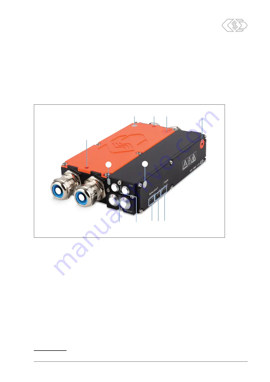
Fig. 3-1 shows the connections of an HV BM 1.2 . The module versions HV BM 1.1 and HV BM 3.1
are equipped with only one PG gland
①
on each side of the housing and they lack the holes
for the threaded bolts
⑩
. As for the HV BM 3.1, the connection sockets (CAN/EtherCAT®) are
also located on the opposite side. Otherwise these modules are identical to the HV BM 1.2.
The LED indicators
⑦
,
⑧
,
⑨
are located in the front panel of the module housing. Depending
on the module version, the sockets for CAN
②
, EtherCAT®
③
and power supply
④
are embed-
ded in the left or the right side of the housing.
⑤
⑦ ⑧⑨
⑩
⑩ ⑪
⑫
⑪
④
②
②
③
①
①
⑫
⑫
⑥
Fig. 3-1: HV BM 1.2, front view
1. PG glands
2. CAN sockets
(
→ chapter 4.4.2.1 "CAN sockets"
)
3. EtherCAT®
IN
socket (
→ chapter 4.4.2.2 "EtherCAT® IN socket"
)
4. EtherCAT®
OUT
socket (
→ chapter 4.4.2.3 "EtherCAT® OUT socket"
5. EtherCAT® bus status LED indicator (
→ chapter 3.3.1 "Status LED indicator for EtherCAT® bus"
)
6. CAN bus LED indicator (
→ chapter 3.3.2 "CAN bus LED indicator"
7. LED indicators for EtherCAT® bus (
→ chapter 3.3.3 "EtherCAT® bus LED indicators"
8. LED indicators for EtherCAT® measurement channels (
9. LED indicators for CAN measurement channels (
→ chapter 3.3.4 "Measurement channel
10. Holes for threaded bolts for fastening multiple HV BM to each other.
11. GORE™ membrane venting grooves with corresponding sticker
12. Contact surfaces for measuring the resistance of protective earth (PE) to cover
1
1 The positions of the contact surfaces vary depending on module type and hardware revision.


