Page 8
Fiberlink® 3X3X Series User’s Manual
Fiberlink® 3X3X Series
Data Configration Procedure
.
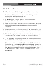
The following instructions describe the typical data configuration procedure:
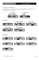
1) Set the rear panel DIP switches of the transmitter for the desired protocol.
See page 9 for DIP switch configuration settings.
2) Set the rear panel DIP switches of the receiver for the desired protocol.
See page 9 for DIP switch configuration settings.
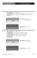
3) Data terminal block positions 1 through 6 can be used as data inputs or data outputs
depending upon the protocol selected. Refer to page 10 for terminal block
configuration.
4) After the terminal blocks have been wire appropriately, plug them into the rear panel
connectors labels DATA/ALARM on both the transmitter and receiver units.
5) If there is no fiber optic cable connecting the transmitter and receiver at this time,
connect an optical cable to both the transmitter and receiver units at this time.
5) Turn on the power for both the transmitter and receiver units. When power is applied
the green POWER LED on each unit will illuminate.
If data is present, the transmitter’s TX LED and the receiver’s RX LED will illuminate.
If a fiber optic cable is connected to both the transmitter and receiver but there is no
data present, both the transmitter’s TX LED and the receiver’s RX LED will remain off.
If you feel this is in error check the data SIP switch settings for your desired protocal
on both the receiver and the transmitter units then verify the wiring of the data
terminal blocks.
Data Configuration Procedure


