Crystal Vertical 120 Скачать руководство пользователя страница 11

10

3. Installation

WARNING: Installation must be carried out by a qualified engineer.

This section is provided for information purposes only and must be checked and adapted if
necessary according to the actual installation conditions.

3.1 Pre-requirements
Equipment necessary for the installation of your heat pump:

Power supply cable suitable for the unit’s power requirements.

A By-Pass kit and an assembly of PVC tubing suitable for your installation as well as stripper, PVC adhesive.

A set of wall plugs and expansion screws suitable to attach the unit to your support.

Suitable fastening studs may be used to raise the unit.
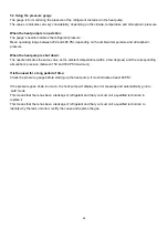
3.2 Location

Please comply with the following rules concerning the choice of heat pump location.
-

The unit’s future location must be easily accessible for convenient operation and maintenance.

-

It must be installed on the ground, fixed ideally on a level concrete floor. Ensure that the floor is sufficiently

stable and can support the weight of the unit.
-

A water drainage device must be provided close to the unit in order to protect the area where it isinstalled.

-

If necessary, the unit may be raised by using suitable mounting pads designed to support its weight.

-

Check that the unit is properly ventilated, that the air outlet is not facing the windows of neighbouring buildings

and that the exhaust air cannot return. In addition, provide sufficient space around the unit for servicing and
maintenance operations.
-

The unit must not be installed in an area exposed to oil, flammable gases, corrosive products, sulphurous

compounds or close to high frequency equipment.
-

To prevent mud splashes, do not install the unit near a road or track.

-

To avoid causing nuisance to neighbours, make sure the unit is installed so that it is positioned towards the

area that is least sensitive to noise.
-

Keep the unit as much as possible out of the reach of children.
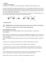
≥ 0.5m

≥ 0.5m

≥ 0.5m

≥ 0.5m

≥ 0.5m

≥ 0.5m

Dimensions in mm.

Place nothing less than one metre in front of the heat pump.

Leave 50 cm of empty space around the sides and rear of the heat pump.

Do not leave any obstacle above or in front of the unit!

≥ 2.5

AIR

Содержание Vertical 120

Страница 1: ...INSTALLATION AND USER MANUAL for your heat pump Crystal Vertical 120 200...

Страница 2: ...o the surrounding area Before starting work the environment of the equipment should be checked to ensure that there is no risk of flammability No smoking signs must be posted 6 Ventilated area Make su...

Страница 3: ...atible with the actual installation conditions and does not exceed the maximum limits authorised for this particularproduct In the event of a defect and or malfunction of the heat pump the electricity...

Страница 4: ...orts 11 3 6 Hydraulic connection 12 3 7 Electrical installation 14 3 8 Electrical connection 15 4 Use 16 4 1 Wired remote control 16 4 2 Operating mode selector 17 4 3 Setting the clock 18 4 4 Program...

Страница 5: ...on may undertake installation start up servicing and repairs in compliance with current standards Before operating or undertaking any work on the equipment installation commissioning usage servicing t...

Страница 6: ...ons Brazing should be performed by a qualified welder When replacing a defective refrigerant component use only parts certified by our technical department When replacing pipe work only copper pipes c...

Страница 7: ...up to 90 energy savings compared to a conventional heating system Clean efficient and environmentally friendly R32 refrigerant Reliable high output leading brand compressor Wide hydrophilic aluminium...

Страница 8: ...7 C Capacity KW 7 25 2 93 10 85 5 03 Power input KW 2 04 0 63 2 58 1 05 Input current A 8 96 2 77 11 33 4 61 EER 4 65 3 55 4 77 3 56 Air 15 C Water 26 Capacity KW 4 33 1 00 6 95 1 75 Power input KW 1...

Страница 9: ...8 D C 2 4 Unit dimension B Crystal Vertical 120 Crystal Vertical 200 A 735 735 B 570 570 C 550 550 D 540 540 E 600 600 F 414 414 G 87 87 H 160 160 Made in mm E A F G H...

Страница 10: ...t 14 4 way valve 4 Electronic Expansive Valve 15 Electrical Control Box 5 Compressor 16 Controller 6 Heat Exchanger 17 Control Panel 7 Water Flow Switch 18 Display Panel 8 Fan Motor 19 Front Panel 9 F...

Страница 11: ...weight of the unit A water drainage device must be provided close to the unit in order to protect the area where it isinstalled If necessary the unit may be raised by using suitable mounting pads des...

Страница 12: ...pump in the winter as this will allow the water to freeze and block the tube This will then allow water and ice to back up into the unit and cause damage which will not be covered under the Warranty P...

Страница 13: ...n with the By Pass kit WARNING Do not run water through the hydraulic circuit for 2 hours after applying the adhesive Step 1 Take the necessary steps to cut your pipes Step 2 Make a straight perpendic...

Страница 14: ...Pass assembly for more than one heat pump The filter located downstream of the heat pump must be regularly cleared so that the water in the system is clean thus avoiding the operational problems assoc...

Страница 15: ...ted by a 30 mA di erential switch The heat pump must be connected to a suitable D curve circuit breaker see table below in accordance with current standards and regulations in the country where the sy...

Страница 16: ...nnect the heat pump Step 1 Detach the electrical side panel with a screwdriver to access the electrical terminal block Step 2 Insert the cable into the heat pump unit by passing it through the opening...

Страница 17: ...16 4 Use...

Страница 18: ...or vice versa the heat pump will restart after 10 minutes When the incoming water temperature is less than or equal to the required temperature set point tempera ture 1 the heat pump will switch to he...

Страница 19: ...start time Step 4 Adjust the hours with the buttons and Step 5 Press to switch to minutes Step 6 Adjust the minutes with the buttons and Step 7 Press to program the stop time Step 8 Adjust the hours w...

Страница 20: ...icing function Long and 3 seconds to enter forced de icing the symbol flashes 4 7 Enable Disable LEDs Hold and for 3 seconds to activate or deactivate the front LEDs The LEDs are reactivated automatic...

Страница 21: ...Description Values 01 Water inlet temperature 30 99 C 02 Water outlet temperature 30 99 C 03 Ambient temperature 30 99 C 04 Air outlet temperature 0 125 C 05 Air inlet temperature 30 99 C 06 Outside...

Страница 22: ...The system s settings can be checked and adjusted via the remote control by following these steps Step 1 Keep pressing 3s on until you enter the settings verification mode Step 2 Press and for see the...

Страница 23: ...t of the temperature water inlet 5 15 C 0 C Adjustable 10 Reserved Do not adjust Reserved 11 Auto activation time before de icing commences 20 90 min 45 min Adjustable 12 De icing activation temperatu...

Страница 24: ...l from around the unit Operation 1 Activate the unit s power supply protection di erential switch and circuit breaker 2 Activate the circulating pump if it is not servo controlled 3 Check the By Pass...

Страница 25: ...the same value as the ambient temperature within a few degrees and the corresponding atmospheric pressure between 150 and 350 PSI maximum If left unused for a long period of time Check the pressure g...

Страница 26: ...refrigerant It would be wise for heat pumps that are used on Ponds and non Chemically treated Hot Tub users to flush out the titanium heat exchanger every few months as Bio Film will build up here all...

Страница 27: ...in the system when the heat pump is working A heated pool must be covered to avoid any loss of heat 7 Repairs 7 1 Breakdowns and faults In the event of a problem the heat pump s screen displays a fau...

Страница 28: ...temperature Sensor disconnected or defective Reconnect or replace sensor 15 Water intake temperature sensor malfunction Sensor disconnected or defective Reconnect or replace sensor 16 Outside coil tem...

Страница 29: ...ramming port CN7 OUT7 OUT6 YLW or BLK Low Pressure Switch OUT5 BLU WHI RED Emergency switch BRN BRN Water flow switch OUT4 RED WHI 4 way valve OUT3 Reserved BLU BLU OUT2 CN IN1 IN2 IN3 IN4 IN5 OUT1 Co...

Отзывы: