


Crystal Vision
Hardware installation
27/10/2006
12
GPI 36 User Manual R3.0
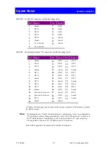
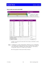
Rear module connections with RM37
RM37
Description
RM37
•
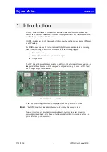
12 modules per 2U frame, 6
per 1U frame & 2 per DTB
•
All frame slots can be used
Pin
Signal
Pin
Signal
Pin
Signal
1c
GPI 01
22c
GPI 13
25a
GPI 25
2c
GPI 02
21a
GPI14
28c
GPI 26
1a
GPI 03
22a
GPI15
27a
GPI 27
2a
GPI 04
28a
GPI 16
9c
GPI 28
4c
GPI 05
9a
GPI 17
13c
GPI 29
5c
GPI 06
10a
GPI 18
13a
GPI 30
5a
GPI 07
12c
GPI 19
16c
GPI 31
4a
GPI 08
15c
GPI 20
16a
GPI 32
10c
GPI 09
18a
GPI 21
19a
GPI 33
12a
GPI 10
18c
GPI 22
21c
GPI 34
15a
GPI 11
24c
GPI 23
21a
GPI 35
19c
GPI 12
25c
GPI 24
27c
GPI 36
6a 8a 11a 14a 17a 20a 23a 26a 29a 31a 3c 6c 8c 11c 14c 17c
20c 23c 26c 29c 31c
Ground
7a 30a 32a 7c 30c 32c
No connection
A 500mA +5Volt supply may be found on the remote connectors of the frames in which
the GPI36 is fitted.
Note:
On Desktop boxes, 1U and 2U frames, Remote 1 and Remote 3 are 26 way high density
‘D’ type female sockets. Frame ground is pin 2 and +5V @500mA is pin 1 in each case.
On 2U frames Remote 2 and Remote 4 are 26 way high density ‘D’ type male plugs.
Frame ground is pin 6 and +5V @500mA is pin 15 in each case.
Refer to the appropriate frame manual for further information.


