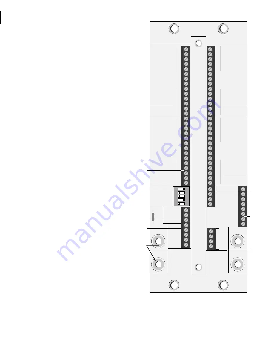
MRX-24/24S “T-Board” For
External Connections
MRX-24
T-BOARD
460015
+12 V
GND
BOARD
ADDRESS
AUX OUT
AUX IN
16
8
4
2
1
AUX GND
+12 V
GND
IQ BUS
+IN
–IN
+OUT
–OUT
GND
SB8
SB7
SB6
SB5
SB4
SB3
SB2
SB1
SLAVE
BUS
CONNECTIONS
SB GROUND
SB +12
PULLUP
REL 1A
REL 1B
REL 2A
REL 2B
REL 3A
REL 3B
REL 4A
REL 4B
REL 5A
REL 5B
REL 6A
REL 6B
REL 1A
REL 1B
REL 2A
REL 2B
REL 3A
REL 3B
REL 4A
REL 4B
REL 5A
REL 5B
REL 6A
REL 6B
GP3 COM A
GP3 COM B
GP4 COM A
GP4 COM B
GROUP 3
GROUP 4
12
3
4
5
REL 1A
REL 1B
REL 2A
REL 2B
REL 3A
REL 3B
REL 4A
REL 4B
REL 5A
REL 5B
REL 6A
REL 6B
REL 1A
REL 1B
REL 2A
REL 2B
REL 3A
REL 3B
REL 4A
REL 4B
REL 5A
REL 5B
REL 6A
REL 6B
GP1 COM A
GP1 COM B
GP2 COM A
GP2 COM B
XB4
XB3
XB2
XB1
GROUP 2
GROUP 1
G
K
I
J
H
N
L
M
can handle one ampere at 100V continuously, or 0.5 A at 100V while switch-
ing. Relays are arranged as four groups of six. One side of each of the six
in a group are tied together to an unswitched common external connec-
tor. Refer to the block diagram shown on the next page. By tying relays
together at the T-board, any form of matrix can be formed with the neces-
sary number of MRX modules.
B. Edge Connector
When installing the MRX module into the cage, the edge connector seats
into a female edge connector mounted to the T-board.
C. MRX Microprocessor
Only master MRX units have an installed microprocessor. Slave units op-
erate by special communication, called a Slave Bus, with a master unit.
D. IQ Component Address
Both master and slave units have this DIP switch on their circuit boards,
but the address is only used with master units. On slave units this set of
switches is out of circuit and unused. Up to 250 master units can be used
on any one Crown Bus serial data loop to the system interface.
E. Battery Backup
Master units have a battery installed to maintain processor memory when
the +12 VDC supply is lost. This battery will maintain memory for at least
60 days.
F. Battery Backup Enable Jumper
A jumper is provided to disable battery backup if that feature is not de-
sired.
G. Relay Connectors
Connections to relay contacts are made via mini-barrier strip pins.
H. Power Supply Connection
Plated holes are provided for connection of +12 VDC and ground from
an IQ-LPS or other 12 volt supply. Holes are sized to accept #6 screws.
I. Sensing Aux Port
A mini-barrier block connector is provided for auxiliary functions. +10
VDC at 20 mA is output at Aux Out when switched on. Aux In senses
voltage: if +3 to +20 VDC is sensed (with respect to Aux Ground), the
microprocessor will interpret the voltage as a digital high (on condi-
tion). Note that although both the master and slave versions have this
connection, only the master’s Aux port is operational.
J. Crown Bus
A 5-pin mini-barrier block connector is provided for digital communi-
cation via the Crown Bus serial data loop to other IQ components. This
connector is only used by master units (present on both).
K. Board (Slave) Address
Master units communicate with other IQ system components via Crown
Bus, and thus use the IQ Address setting (item D). Slave units use the
Board Address to identify themselves to the master unit. The five position
switch allows for 31 valid settings (a setting of 0 is not valid), thus up to 31
slaves can be operated from one master. Board Address settings have
no effect on master units.
L. Slave Bus (SB1-8)
An 8-pin mini-barrier block connector is provided for digital communica-
tion via the Slave Bus between a master unit and its slaves. This is a
parallel communications bus and must tie into all slaves being operated
by one master. For complete communication the XB4 and SB Ground
connections must also be made, as detailed under items M and N.
M. Extended Bus (XB1-4)
A 4-pin mini-barrier block connector is provided for Extended
Bus communication. With present firmware, only the XB4 pin is


