Cross Technologies 2016-25-01 Скачать руководство пользователя страница 11

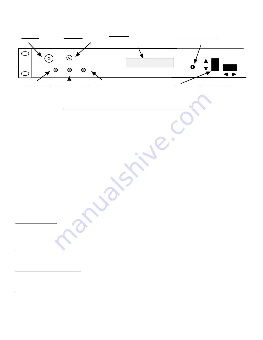
2.3  Front Panel Controls and Indicators - The following are the front panel controls and indicators.
  

MENU

EXECUTE

F=2250.000     G=+10.0

REMOTE

POWER

LCD DISPLAY
Display shows frequency in MHz and 
Gain in dB, and is used to change 
settings in Program mode.

S1 - MENU/EXECUTE BUTTON
Press this to get into Program mode 
and  to execute any changes.

DS6 - POWER LED
Green LED indicates 
presence of DC power.

DS1 - REMOTE LED
Yellow LED indicates 
remote operation.

S2 - VERT. TOGGLE
Vertical toggle switch that controls 
values in the Menu items when in 
program mode. Does not function in 
the normal display mode

S3 - HORIZ. TOGGLE
Horizontal toggle switch that 
controls which values are being 
adjusted. Does not function in the 
normal display mode

ALARM 

DS3 - ALARM LED
Red LED indicates 
downconverter alarm.

IF MONITOR

RF MONITOR

IF MONITOR
-20db IF Monitor Port

RF MONITOR
-20db RF Monitor Port

FIGURE 2.3  2016-25-01 Front Panel Controls and Indicators

2.4  Auto 10 MHz Reference Mode

When the frequency converter’s reference mode is set to AUTO it will lock to an external reference and 
automatically switch to the internal reference if both PLL circuits become unlocked.  Once the converter 
switches to the internal reference it will remain there until the “Reference Fault” state is cleared. The reference 
fault state is displayed on the front panel and is reported via the “{S2}” M&C status query. Converters with the 
Ethernet M&C option will also report the reference fault via the web browser interface. Converters with the 
Et SNMP option will also report the reference fault via an SNMP object in its MIB.   

When the reference fault state is cleared the converter will attempt to lock to the external reference.

The reference fault state can be cleared via the front panel or via remote M&C commands.
These methods are described below.

Front Panel Method
Navigate to the reference mode select menu.  Any activity on the front panel up or down switches will 
clear the reference fault.

Remote M&C Method
Send the command “{CF}” to clear the reference fault state.

Web Browser Interface Method
Click on the “Clear Fault” button near the bottom of the web page.

SNMP Method

Issue a SET command with a value of 0 to the reference fault object in the MIB.

2016-25-01 Manual _Rev A


     Page 11

                               3/26/09

Содержание 2016-25-01

Страница 1: ...ies Inc but may be reproduced or duplicated without the prior permission of Cross Technologies Inc for purposes of operating the equipment When ordering parts from Cross Technologies Inc be sure to in...

Страница 2: ...a period of one year after shipment to customer Cross Technologies Inc s obligation under this warranty is limited to repairing or at Cross Technologies Inc s option replacing parts subassemblies or...

Страница 3: ...ar on the LCD display Connectors are N type for RF In BNC for IF Out 10 MHz In 10 MHz Out and IF Monitor SMA for RF Monitor and 1st LO Monitor The unit is powered by a 100 240 10 VAC power supply and...

Страница 4: ...kHz 1kHz 100 Hz dBC Hz Phase Noise Freq Controls Indicators Frequency Selection Direct readout LCD manual or remote selection Gain Selection Direct readout LCD manual or remote selection Power Alarm R...

Страница 5: ...7 8 9 Female DB 9 PC Com Port Male DB 9 2015 16 17 M C Port M C Cable Diagram Cross Technologies Frequency Converters RX RX TX TX DTR SG DSR RTS CTS SG Connector Rear panel DB 9 male J10 Pinouts Pinou...

Страница 6: ...tus Requests Command Syntax Description Command Status aaS1 Returns aaS1bbbbbbbccde where bbbbbbb Rx frequency cc Rx gain d 0 non inverted Receiver 1 inverted e 0 Summary Alarm 1 Alarmed 0 Normal 10MH...

Страница 7: ...should be used ONLY when RS 485 OPTION Q is selected Table 1 2 2016 25 01 Comm mands Commands Command Syntax Description Set Receiver Frequency aaC2xxxx where xxxxxxx 7 characters Range 200000 to 2500...

Страница 8: ...quipment is not compromised Additional space between unit may be required E Circuit Overloading Consideration should be given to the connection of the equipment to the supply circuit and the effect th...

Страница 9: ...inch deep chassis A switching 12 24 5 VDC power supply provides power for the assemblies The 2016 25 01 can be secured to a rack using the 4 holes on the front panel Figure 2 1 shows how the 2016 25...

Страница 10: ...2 RF IN 2000 2500 MHz 70 to 20 dBm input 50 BNC female see Table 2 2 for other options J20 ETHERNET CONNECTION RJ45 Ethernet Connector 1st LO MONITOR Sample of the 1st LO of the downconverter FIGURE 2...

Страница 11: ...ock to an external reference and automatically switch to the internal reference if both PLL circuits become unlocked Once the converter switches to the internal reference it will remain there until th...

Страница 12: ...nd the input level provided See Section 2 5 Menu Settings 6 Be sure DS6 green DC Power is on and DS2 red Alarm is off Figure 2 3 7 AC Fuse The fuse is a 5 mm X 20 mm 2 amp slow blow Type T and is inse...

Страница 13: ...ect RS232 RS422 RS 485 or Ethernet option W85 Remote Operation option Q Menu 8 Select Remote Address for Unit RS485 only option Q Save Menu When R is selected in any above menu or the next menu item a...

Страница 14: ...may desire 2 6 3 Control Switches 1 Menu Execute Any change to the programming of the unit must be initiated by pressing the Menu Execute switch and completed by pressing the Menu Execute switch 2 Hor...

Страница 15: ...quency F 2250 R Pressing the Up Down switch down will toggle the display to F 2350 R By using the horizontal rocker switch the cursor can be moved left or right F 2350 R NOTE CHANGES DO NOT TAKE PLACE...

Страница 16: ...en push the Menu Execute switch to get to the Gain setting G 00 R Press the Up Down switch to change the gain in 1 or 10 dB steps G 10 R By using the horizontal rocker switch the cursor can be moved l...

Страница 17: ...own Gain 0 to 50 Menu 3 Set Unit to Remote Operation Menu 4 Select Non inverting or Inverting Spectrum Menu 5 Select External 10 MHz Reference option E Menu 6 Select 10MHz Output option E Menu 7 Selec...

Страница 18: ...cy converter s Ethernet port to the LAN using a normal RJ 45 cable Use any PC on the LAN to connect to the frequency converter 1 2 Ethernet Configuration Each frequency converter must be configured wi...

Страница 19: ...r the IP address Subnet mask and Gateway address with delimiter dots example 192 168 192 47 1 3 Webpage M C Enter the following address in a web browser to access the M C webpage http ip address seria...

Страница 20: ...stablish such a Telnet connection using Windows XP s Hyper Terminal utility Start the Hyper Terminal application and select New Connection from the File drop down menu The next screen is a Connect To...

Страница 21: ...write strings After setting your desired community strings you will be prompted to Enter IP addresses for SNMP traps You must enter at least one and up to four IP addresses of SNMP managers that will...

Страница 22: ...Figure 2 F Device Server Configuration Menu 2016 25 01 Manual _Rev A Page 22 3 26 09...

Страница 23: ...INC 6170 Shiloh Road Alpharetta Georgia 30005 770 886 8005 FAX 770 886 7964 Toll Free 888 900 5588 WEB www crosstechnologies com E MAIL info crosstechnologies com Printed in USA 2016 25 01 Manual _Rev...

Отзывы: