2.5 Operation
2.5.1 Operating the 2000-02 Power Supply
1. Connect the DC power output to the Series 2000 unit (or other unit) (Figure 2.3).
2. Connect the 2000-02 to 100-240 ± 10% VAC, 47-63 Hz AC power.
3. Be sure DS1 (green, DC POWER) is on (Figure 2.2).
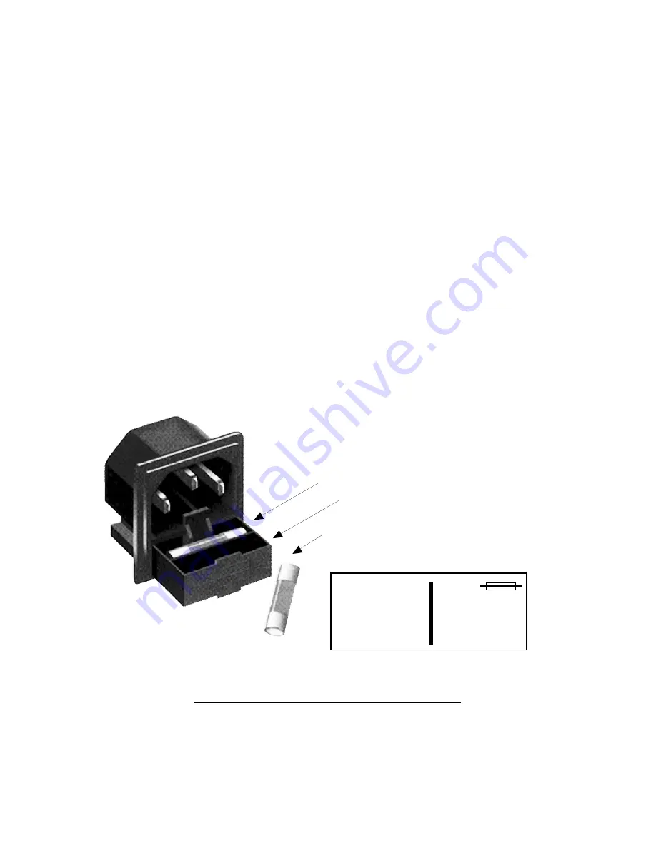
4. AC Fuse - The fuse is a 5 mm X 20 mm, 2 amp slow blow (Type T) and is inserted in the far slot in the
drawer below the AC input as shown in Figure 2.4. There is a spare fuse in the near slot. If a fuse
continues to open, the power supply is most likely defective.
2.5.2 Replacing the Fuse in the Rear Panel Fuse Box
1. Remove the 100-240 ± 10% VAC, 47-63 Hz AC power from the 2000-02.
2. Pull out the fuse box below the AC Input connector (Figure 2.3).
3. Pry out the fuse in the back slot and measure it to see if it is open.
4. If the fuse is open, determine the cause of the blown fuse and repair this.
5. After the cause of the blown fuse is corrected, replace the open fuse with the 2.0 amp fuse
in the front section.
6. Apply 100-240 ± 10% VAC, 47-63 Hz AC power to the 2000-02 and be sure DS1 (green, DC POWER)
is on (Figure 2.2).
AC Fuse - 2 amp slow blow (Type T),
5 mm X 20 mm
FUSE DRAWER
SPARE FUSE
~
INPUT
100-240± 10%VAC
47-63 Hz
2A MAX
FUSE
TYPE T 2A GDC
250 VOLT
FOR 100 - 240 V~
~
FIGURE 2.5 Fuse Location and Spare Fuse
2000-02 Manual, Rev. C
Page 7
01/27/10


