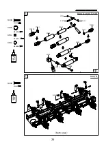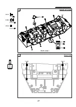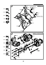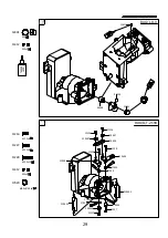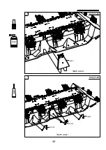
44
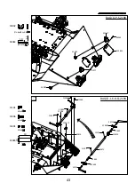
43
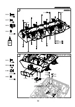
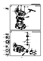
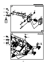
11105
M3x6
11106
M3x8
11105
11106
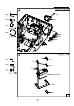
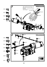
14102
40
BAG/Q
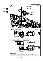
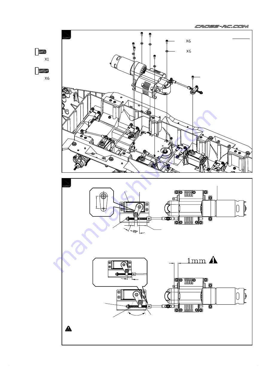
Servo arm installation
1. 1 Check to remote control's instruction for get servo using and setting method.
1.2 Make sure the servo is in neutral position before installation, as shown in the drawing to keep
the transmission rod in its state (low gear), the arm is mounted on the servo, and the servo
doesn't put pressure on the shift rod after installation completed
2. Adjusting servo stroke and result to spring decrement in the 2-3mm after into high speed gear.
Make sure the servo is operated in a suitable stroke, it's may result in damage to the servo or
transmission gearbox parts if the servo or shift rod continues to exert a large force.
WARNING
Servo stroke adjustment
Amount of compression 2~3 mm
Spring #1
Spring #2
Servo stroke
Nut
Transmission gear box
Servo arm
Transmission rod
Servo
22mm
a
b
a<b
Содержание BT8
Страница 3: ...2 2181 2182 2198 X 1 X 1 X 1 ...
Страница 4: ...3 2187 2197 2237 2193 2196 2192 X 1 X 1 X 1 X 1 X 1 X 1 ...
Страница 5: ...4 2186 2195 2238 2188 2184 X 1 X 1 X 1 X 1 X 1 ...
Страница 6: ...5 2194 2189 X 1 X 1 ...
Страница 7: ...6 2236 2185 X 1 X 1 ...
Страница 9: ...223904 223901 223902 223903 X 3 X 2 8 2239 2105 210 X 1 21004 21005 21006 21008 21009 ...
Страница 18: ...17 1 BAG B C Q 11315 43319 43320 44149 11315 M2 5x6 THREAD LOCK ...
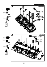
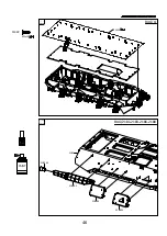
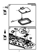
Страница 45: ...51 218601 Both sides 52 Both sides 218902 218901 218902 GLUE 44 PAINT BAG 2186 BAG 2189 ...
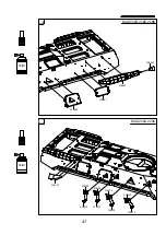
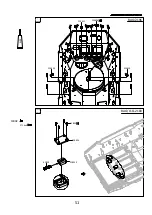
Страница 47: ...55 56 218343 218801 218602 218603 2181 PAINT 46 11322 M3x10 BAG Q 11322 BAG 2181 2183 2186 2188 ...
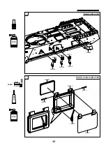
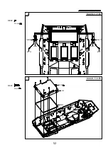
Страница 52: ...66 65 219611 219610 219610 219609 GLUE 11802 11802 ST1 4x4 218354 218353 41829 51 BAG 2196 BAG O Q 2183 ...
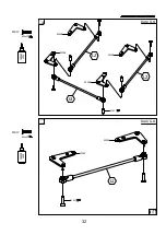
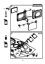
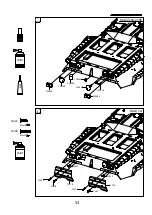
Страница 68: ...97 96 218504 218501 218507 223802 218501 11907 M3x6 11907 PAINT 67 BAG 2185 2238 BAG Q ...
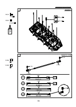
Страница 74: ...108 109 Both sides 11802 71281 11802 ST1 4x4 73 88004 88003 BAG I Q W BAG V ...
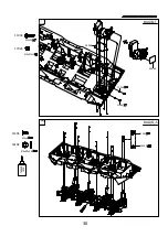
Страница 76: ...112 GLUE PAINT 2187 41804 X 8 Both sides 12204 12204 M4 12204 12204 12204 75 BAG J Q 2187 ...

