10. POWER
UP
When the DO7e is fi rst switched on, an internal self-test is automatically performed. The display
indicates -8888 followed by PASS and then switches to standby mode ready for measurement.
Should the internal checks indicate an error, then the display will read “HELP”. Contact our
Service Department or your local agent for assistance.
The DO7e will perform an automatic zero sequence and fi nally sets to the following default
start-up mode ready for use. The selected measuring range will be 600
Ω
, and the DO7e will
then be in stand-by mode. The display will blank after approx. 25 seconds.
11. MEASUREMENT
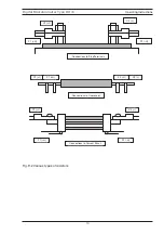
Connect the resistance to be measured (Rx) to the measuring terminals in accordance with the
diagram on the instrument panel. Select the range required or Auto range, and the current
measurement mode, ie. +, -or average. The LED lamps will light to indicate which buttons are
active. To initialise the measurement, press the
MEAS
button, a single measurement will be
initialised and the value held on the display for approximately 25 seconds. After 25 seconds
have elapsed the display will blank with only the range LED alight, the last measured value
may be recalled to the display by pressing the
MEAS
key. To make another measurement the
MEAS
key should be pressed again Should you wish to initialise a continuous reading, then
press and hold the MEAS key until a long bleep is heard this will lock the measurement in
continuous mode. Note continuous measurement is not possible on the lowest 6m
Ω
range. The
measurement will continue until the
MEAS
key is pressed again. The DO7e will automatically
power off after 5 minutes with no key activity to preserve battery life. Note: the
MEAS
key LED
will be lit whilst a measurement is in progress.
Current Mode
The current mode can be set to measure with +I, -I or AVE. The
AVE
mode should be selected
for all measurements that are not inductive, as this eliminates errors due to thermal emf in the
measurement circuit or test leads. In the AVE mode the DO7e measures with the current in both
directions and displays the average of the two readings. For measurement of inductive circuits
the measuring current should either be set in + or - mode.
Over-Range
The display will indicate - - - -.
Select a higher range.
Open Circuit Lead
O/C LEAD LED will light and the display will indicate - - - - if the instrument detects that the lead
resistance is too high. ( The C terminals are checked for compliance voltage). Measurement
cannot be made if this warning message is displayed. This warning will also be displayed if the
internal protection fuse is open-circuit.
When in STANDBY mode this LED will always be lit.
Digital Microhmmeter Type DO7e
Operating Instructions
11


