


1770 S. Tapo Street, Simi Valley, CA 93063 Phone: 800.998.6880
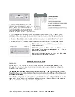
4. Hand-tighten Antenna connectors to
“GPS ANT” and “MODEM ANT” outlets on
Device. Do not power the device without
the GSM connector secured to the device.
Powering up the Device without the GSM
connector secured may result in product failure.
5. Plug in supplied wire harness to Device. Ground/Black wire should be on far left side of Device
matching to (Ground) on Device front panel. Match Power/Red wire to VIN (Voltage IN) on Device.
6. Make sure the vehicle is parked outside and has a clear view of the horizon for GPS to “lock in”.
7. Observe LED status to confirm proper installation and if device is receiving GPS/GSM signals
PWR
= this LED w i l l move to a solid RED state as soon as the device
receives constant
p
ower
USR2
= GPS signal. When the GPS has locked on, this LED w i l l move to a
solid RED state. It may take u
p
to fifteen minutes to lock on, although
generally less than five minutes.
USR1
= GSM /Cellular status. This LED should move to a solid GREEN state
within one minute of the Device being
p
owered u
p.
Starter Disable with ECM
Background
If you’re doing a starter interrupt i n s t a l l on a vehicle with ECM, then the standard installation does
not apply. The starter wire goes into an onboard computer, generally carrying a low voltage into
i t instead of the standard 12.
You need to have a voltage meter, not a standard “Ice Pick”! The l i ght will come on with
the pick and give you a false reading! I f you tap a wire with a low voltage (3-5 volts) you will
lock down the vehicle!
Follow the low voltage wire from the ignition key to the ECM. Use your voltage meter to ensure that
i t is a 12 volt supply coming out. Once you’ve located the proper 12 volt wire after the ECM, proceed
with the regular starter interrupt instructions using this wire.


