ZUMNET-GATEWAY
Z
ū
m™ Wireless Gateway
Installation Guide
Description
The Crestron
®
ZUMNET-GATEWAY is a 2-way RF wireless transceiver designed for use
with products that use the Z
ū
m Net wireless communications protocol. A single
ZUMNET-GATEWAY works with the ZUM-FLOOR-HUB (not included) to provide central
monitoring, management, reporting, and control of lighting systems throughout the
enterprise.
Additional Resources
Visit the product page on the Crestron website (
www.crestron.com
)
for additional information. Use a QR reader application on your
mobile device to scan the QR image.
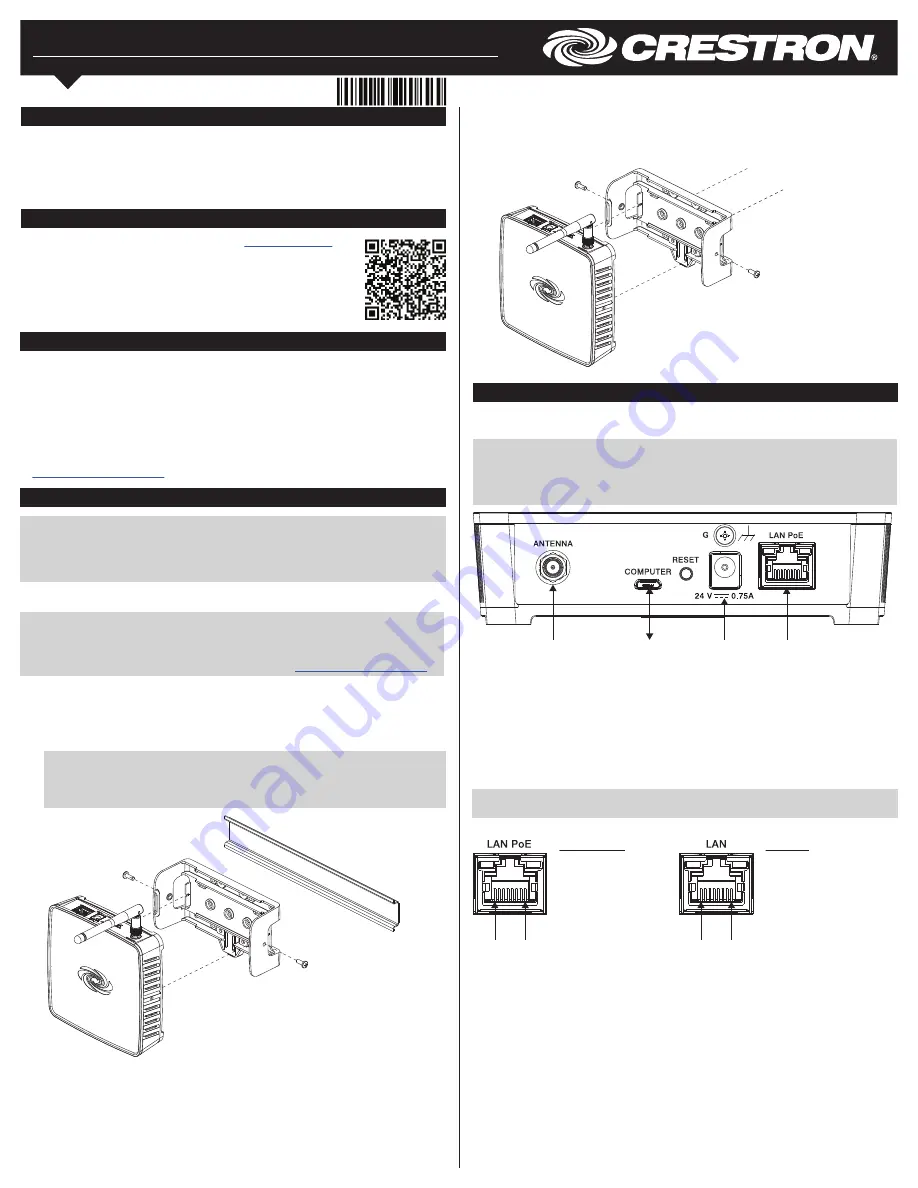
Pin 8 Pin 1
LAN PoE Pins
1. Data Pair 1
2. Data Pair 1
3. Data Pair 2
4. +Vdc
5. +Vdc
6. Data Pair 2
7. -Vdc
8. -Vdc
Pin 8 Pin 1
LAN Pins
1. Data Pair 1
2. Data Pair 1
3. Data Pair 2
4. No Connection
5. No Connection
6. Data Pair 2
7. No Connection
8. No Connection
To supply power using a Crestron PoE injector (sold separately), do the following.
1. Attach the supplied ac power cord to the IEC 320 connector on the PoE (Power over
Ethernet) injector.
2. Use a CAT5 cable to connect the LAN port of the PoE injector to the LAN.
3. Use a CAT5 cable to connect the LAN POE port of the PoE injector to the LAN PoE
input port of the ZUMNET-GATEWAY.
4. Insert the other end of the power cord into an active ac outlet.
NOTE
: In the listing of LAN PoE and LAN pins in the following image, arrows denote
internal pin connections.
LAN PoE and LAN Pin Assignments
USB
to
PC
Power
supply
input
LAN
PoE
input
For
included
antenna
Make Connections
Make the necessary connections as called out in the illustrations that follow. Apply power
after all connections have been made.
NOTE
: When making connections to the ZUMNET-GATEWAY, use Crestron power
supplies for Crestron equipment.
NOTE
: The antenna must be attached directly to the antenna connector. It can be
extended with an optional ANT-EXT-10 Antenna Extender (sold separately).
Installation
NOTE
: Observe the following:
• Install and use this product in accordance with appropriate electrical codes and
regulations.
• A qualified electrician must install this product.
Mount the ZUMNET-GATEWAY onto a DIN rail or onto a vertical flat surface. It can also be
placed onto a horizontal flat surface.
NOTE
: Do not install this gateway within 15 feet (4.6 meters) of other Z
ū
m Net or
infiNET EX
®
gateways.
NOTE
: The ZUMNET-GATEWAY can also be rack mounted. For rack mount installation,
refer to the RMK-IFE-1U Installation Guide (Doc. 7627) at
www.crestron.com/manuals
.
Vertical Flat Surface Mounting
1. Attach the bracket to the wall (wall mount screws not included).
2. Attach the ZUMNET-GATEWAY to the bracket by snapping it into place.
3. Insert the supplied screws through the side of the bracket and secure the gateway.
DIN Rail Mounting
1. Attach the bracket to the DIN rail by snapping it into place.
2. Attach the ZUMNET-GATEWAY to the bracket by snapping it into place.
3. Insert the supplied screws through the side of the bracket and secure the gateway.
NOTE
: When mounting to a DIN rail, use the screw holes only on the side of the
bracket when securing the gateway to the bracket. Using the screw holes on the
back of the bracket to secure the gateway to the bracket will prevent removal of the
device from the DIN rail.
Select the Mounting Location
For optimum performance when installing multiple ZUMNET-GATEWAYs near each other:
• Do not place multiple gateways on the same channel.
• Place gateways at least 15 feet (4.6 meters) apart.
For optimum performance when installing a ZUMNET-GATEWAY:
• Place gateways at least 15 feet (4.6 meters) from the nearest Wi-Fi
®
access point.
• Place gateways at least 6 feet (1.8 meters) from the nearest Bluetooth
®
device.
For more information, refer to Installation and Setup of Crestron RF Products (Doc. 6689)
at
www.crestron.com/manuals
.


