

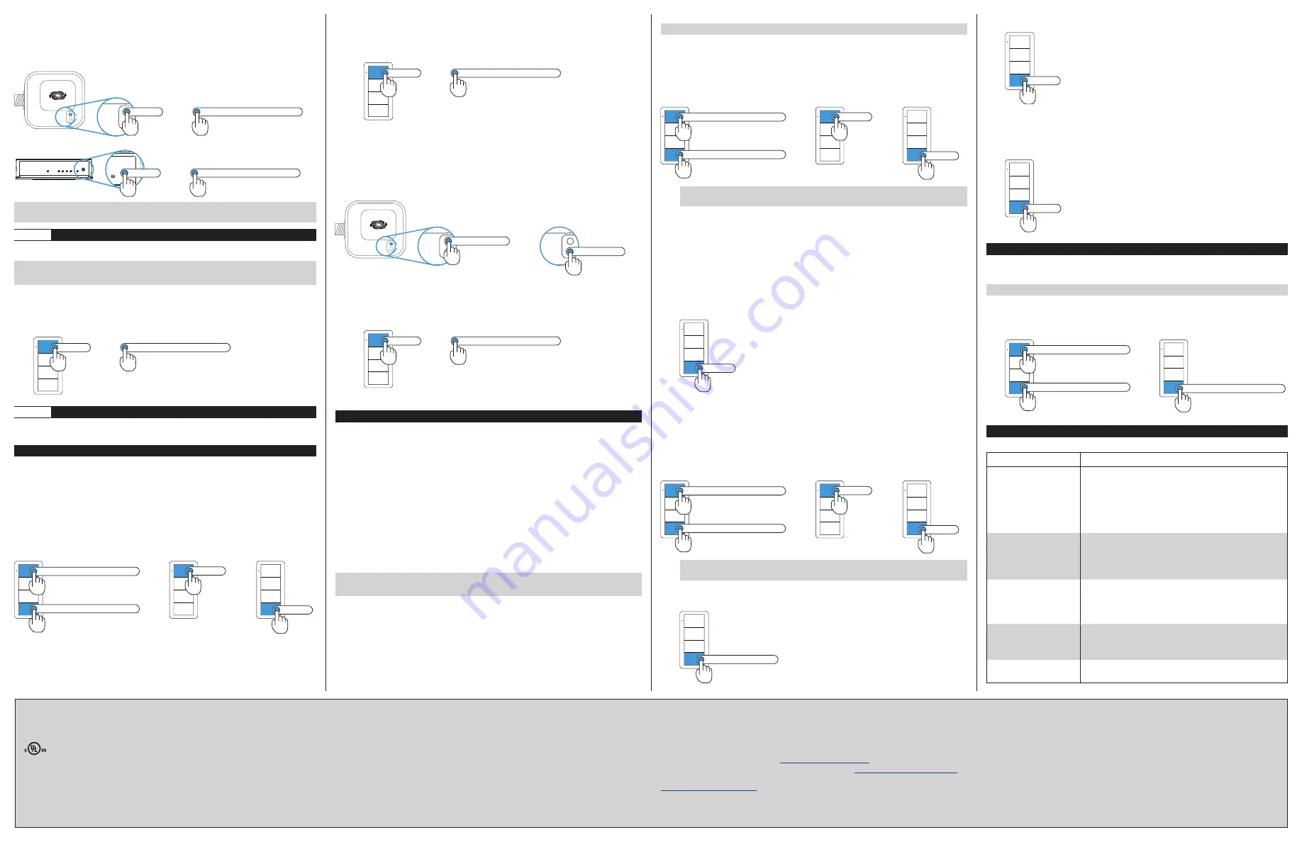
To create a new Zūm space using a J-box device or an AV Bridge:
1. Press the
SETUP
button 5 times.
2. Press and hold the
SETUP
button until the LED on the device lights (about
10 seconds). After approximately 3 seconds, the device LED begins slowly
flashing. This indicates that the Zūm space is now created and in Joining mode,
allowing you to add devices.
TEST
SETUP
TEST
SETUP
Press and hold until LED lights
Press 5x
then
PWR
TX
RX
ERR
NET
SETUP
PWR
TX
RX
ERR
NET
SETUP
Press and hold until LED lights
Press 5x
then
NOTE:
The device that is used to create the Zūm space is automatically added to
the space and does not need to be added in Step 2.
Step 2
Add the ZUMMESH-KPBATT to the Zūm Space
After a new Zūm space is created, add the ZUMMESH-KPBATT while the space is in
Joining mode.
NOTE:
A Zūm mesh device can belong to only one space.
NOTE:
Joining mode ends automatically after 4 minutes.
To add the ZUMMESH-KPBATT:
1. Press the top button 3 times.
2. Press and hold the top button until the LED on the ZUMMESH-KPBATT lights
(up to 10 seconds). The LED on the ZUMMESH-KPBATT will start to flash slowly
to indicate that it has joined the space.
Press and hold until LED lights
Press 3x
then
Step 3
Complete Zūm Space Setup
To finish creating a Zūm space, press any button on a device that is part of the Zūm
space to exit Joining mode.
Add the ZUMMESH-KPBATT to an Existing Zūm Space
Add the ZUMMESH-KPBATT to an existing Zūm space by placing the Zūm space in
Joining mode.
Add the ZUMMESH-KPBATT using a keypad, dimmer, or switch:
1. Enter Joining mode.
a. Press and hold both the top and bottom buttons until the LED lights (about
5 seconds).
b. Press the top button once.
c. Press the bottom button once. The LEDs on all devices in the space (except
battery powered devices) flash slowly to indicate that the devices are part of
the space and that the space is in Joining mode.
Press and hold until LED lights
Press and hold until LED lights
then
then
Press 1x
Press 1x
2. Add the ZUMMESH-KPBATT.
a. Press the top button 3 times.
b. Press and hold the top button until the LED on the ZUMMESH-KPBATT lights
(up to 10 seconds). The LED on the ZUMMESH-KPBATT will start to flash
slowly to indicate that it has joined the space.
Press and hold until LED lights
Press 3x
then
3. Press any button on a device that is part of the Zūm space to exit Joining mode.
Add the ZUMMESH-KPBATT using a J-box device:
1. Enter Joining mode.
a. Press the
SETUP
button 2 times.
b. Press the
TEST
button once. The LEDs on all devices in the space (except
battery powered devices) flash slowly to indicate that the devices are part of
the space and that the space is in Joining mode.
TEST
SETUP
TEST
SETUP
TEST
SETUP
Press SETUP 2x
Press TEST 1x
then
2. Add the ZUMMESH-KPBATT.
a. Press the top button 3 times.
b. Press and hold the top button until the LED on the ZUMMESH-KPBATT lights
(up to 10 seconds). The LED on the ZUMMESH-KPBATT will start to flash
slowly to indicate that it has joined the space.
Press and hold until LED lights
Press 3x
then
3. Press any button on a device that is part of the Zūm space to exit Joining mode.
Change the Default Scenes
The Zūm keypad buttons recall predefined scenes (light levels) that are stored in the
load controllers. The default scenes are ON (scene 1) which sets the loads at 90%,
SCENE 2 which sets the loads at 50%, and SCENE 3 which sets the loads at 10%. Load
controllers can save up to 16 scenes.
There are several methods of changing the default scenes, use the method that
matches your needs.
• End-User Method - Change the light levels for SCENE 2 or SCENE 3 on a
ZUMMESH-KP10ABATT when all load controllers are easily accessible.
• Manual Method - Change the light levels for ON (scene 1) on a
ZUMMESH-KP10BBATT, ZUMMESH-KP10CBATT, or ZUMMESH-KP10DBATT
when all load controllers are easily accessible. Additionally, SCENE 2 and SCENE 3
light levels can be changed on a ZUMMESH-KP10B.
• Remote Method - Change the light levels for ON (scene 1), SCENE 2, or
SCENE 3 on a ZUMMESH-KP10ABATT, ZUMMESH-KP10BBATT,
ZUMMESH-KP10CBATT, or ZUMMESH-KP10DBATT when a load controller is not
physically accessible.
NOTE:
A dimmer lowered to 0% will turn the dimmer off when the scene is recalled.
NOTE:
A load controller that is not bound to the keypad cannot be part of the scene.
End-User Method:
1. Set all load controllers that are bound to the keypad to their desired light level.
2. Press and hold the
SCENE 2
or
SCENE 3
button on the keypad until the LED lights
(about 5 seconds). The light levels are saved to the pressed button.
Manual Method:
NOTE:
Scene 2 and Scene 3 can also be changed.
1. Enter Scene Setting Mode using the keypad that will recall the scene.
a. Press and hold both the top and bottom buttons until the LED lights (about
5 seconds).
b. Press the top button two times.
c. Press the bottom button once. The LED on the keypad flashes its LED two
times every two seconds to indicate that it is in Scene Setting mode. Load
controllers that are bound to the keypad flash their LED rapidly.
Press and hold until LED lights
Press and hold until LED lights
then
then
Press 2x
Press 1x
NOTE:
Scene Setting Mode exits after 5 minutes when initiated from an ac-
powered keypad or 1 minute when initiated from a battery powered keypad.
2. Adjust all light levels.
• Using a dimmer, press and hold the top button to raise the light level or press
and hold the bottom button to lower the light level.
• Using a switch, press the top button to turn the lights on or press the bottom
button to turn the lights off.
• Using a J-box load controller, press and hold the
TEST
button on the J-box
device to cycle-dim the light.
3. Using the keypad that initiated Scene Setting mode, press the
ON
,
SCENE 2
, or
SCENE 3
button to save the light levels to the selected scene button.
4. Repeat steps 2 and 3 for each scene button.
5. Press the bottom button on the keypad 3 times to exit.
Press 3x
Remote Method:
1. Enter Scene Setting Mode using the keypad that will recall the scene.
a. Press and hold both the top and bottom buttons until the LED lights (about
5 seconds).
b. Press the top button two times.
c. Press the bottom button once. The LED on the keypad flashes its LED two
times every two seconds. Load controllers that are bound to the keypad flash
their LED rapidly.
Press and hold until LED lights
Press and hold until LED lights
then
then
Press 2x
Press 1x
NOTE:
Scene Setting Mode exits after 5 minutes when initiated from an ac-
powered keypad or 1 minute when initiated from a battery powered keypad.
2. Press and hold the bottom button of the keypad until a set of lights in the space
flashes on and off twice (about 3 seconds) to indicate that it is selected load. The
lights return to their previous level.
Press and hold 3 sec.
3. Press the bottom button of the keypad to cycle through all of the load
controllers in the Zūm space until the desired load starts flashing.
Press 1x
4. Adjust the light levels by holding the top button on the keypad to raise the light
level or holding the bottom button on the keypad to lower the light level.
5. Press the
ON
,
SCENE 2
, or
SCENE 3
button to save the scene.
6. Repeat steps 3 through 5 until all load controllers and all scenes are defined.
7. Press the bottom button on the keypad 3 times to exit.
Press 3x
Factory Reset
Perform a factory reset when the device is removed from the network or to remove
the configuration settings. The device must also be factory reset if the device is being
moved to a different system.
NOTE:
New-in-box devices do not need to be factory reset before joining a system.
To factory reset the ZUMMESH-KPBATT:
1. Press and hold the top and bottom buttons until the LED lights (about
5 seconds).
2. Press and hold the bottom button until the LED lights (about 10 seconds).
Press and hold until LED lights
Press and hold until LED lights
Press and hold until LED lights
then
Specifications
The specifications for the keypad are listed below.
SPECIFICATION
DETAILS
Construction
Composition
Surface Mounting
Wall Box Mounting
Faceplate
Plastic
Adheres to a smooth, flat wall surface using double-
sided tape (included) or screws (not included)
Mounts to a 1-gang (or larger) electrical box
Requires a decorator-style faceplate (sold separately)
Dimensions
Height
Width
Depth
4.26 in (109 mm)
1.76 in (45 mm)
0.42 in (11 mm)
Power
Battery
Battery Life
Battery (1) CR2032 3 Volt lithium coin cell disposable
battery (included)
Battery Life ≥5 years
Environmental
Temperature
Humidity
32° to 104 °F (0° to 40 °C)
10% to 90% RH (noncondensing)
Enclosure
1-gang mountable;
Requires decorator-style faceplate (not included)
This product is Listed to applicable UL
®
Standards and requirements tested by Underwriters
Laboratories Inc.
Ce produit est homologué selon les normes et les exigences UL applicables par Underwriters
Laboratories Inc.
Federal Communications Commission (FCC) Compliance Statement
This device complies with part 15 of the FCC Rules. Operation is subject to the following
conditions:(1) This device may not cause harmful interference and (2) this device must accept
any interference received, including interference that may cause undesired operation.
CAUTION:
Changes or modifications not expressly approved by the manufacturer responsible
for compliance could void the user’s authority to operate the equipment.
NOTE:
This equipment has been tested and found to comply with the limits for a Class B digital
device, pursuant to part 15 of the FCC Rules. These limits are designed to provide reasonable
protection against harmful interference in a residential installation. This equipment generates,
uses and can radiate radio frequency energy and, if not installed and used in accordance with
the instructions, may cause harmful interference to radio communications. However, there is
no guarantee that interference will not occur in a particular installation. If this equipment does
cause harmful interference to radio or television reception, which can be determined by turning
the equipment off and on, the user is encouraged to try to correct the interference by one or
more of the following measures:
• Reorient or relocate the receiving antenna.
• Increase the separation between the equipment and receiver.
• Connect the equipment into an outlet on a circuit different from that to which the receiver
is connected.
• Consult the dealer or an experienced radio/TV technician for help.
Industry Canada (IC) Compliance Statement
This Class B digital apparatus complies with Canadian ICES-003.
Cet appareil numérique de la classe B est conforme à la norme NMB-003 du Canada.
The product warranty can be found at
www.crestron.com/warranty
.
The specific patents that cover Crestron products are listed at
www.crestron.com/legal/patents
.
Certain Crestron products contain open source software. For specific information, please visit
www.crestron.com/opensource
.
Crestron, the Crestron logo, and Zūm are either trademarks or registered trademarks of
Crestron Electronics, Inc. in the United States and/or other countries. UL and the UL logo are
either trademarks or registered trademarks of Underwriters Laboratories, Inc. in the United
States and/or other countries. Other trademarks, registered trademarks, and trade names
may be used in this document to refer to either the entities claiming the marks and names or
their products. Crestron disclaims any proprietary interest in the marks and names of others.
Crestron is not responsible for errors in typography or photography.
This document was written by the Technical Publications department at Crestron.
©2018 Crestron Electronics, Inc.
Crestron Electronics, Inc.
Installation Guide - DOC. 7865B
15 Volvo Drive, Rockleigh, NJ 07647
(2047761)
Tel: 888.CRESTRON
05.18
Fax: 201.767.7576
Specifications subject to
www.crestron.com
change without notice.


