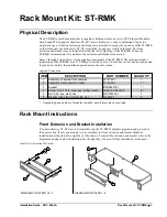
1. With the label on the front extrusion properly orientated, position the four threaded
studs of the extrusion through the four holes of the bracket .
2. Loosely install four lockwashers and four hex nuts onto the studs of the front
extrusion. Using a 1/4-inch hex socket and an inch-pound torque driver, tighten the hex
nuts to
8-inch pounds
(0.90 newton-meters) to secure extrusion.
3. Place the chassis upside down on a clean surface.
4. Turn front extrusion and bracket upside-down and position into open bay of chassis.
5. Align two screw holes in bracket with holes in the chassis. Using a #1 Phillips 1/4-
inch hex bit and an inch-pound torque driver, install two screws and tighten to
8-inch
pounds
(0.90 newton-meters) to secure bracket.
6. Return the ST-RMK to its proper orientation and proceed to the next procedure to install
a module (or ST-CP) into the ST-RMK.
Module (or ST-CP) Installation into ST-RMK
Refer to the procedure below and complete the following steps for proper installation of a module (or
ST-CP) into the ST-RMK.
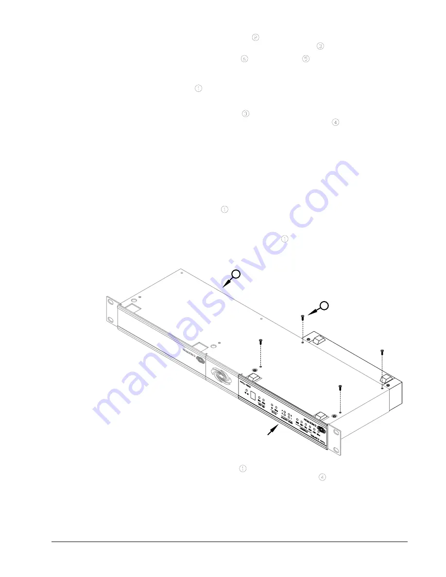
1. Place module into chassis so that front panel of the module is exposed, the two front
rubber feet of the module fit into cutouts in the chassis, and the two rear rubber feet
extend from the rear edge.
2. As shown below, keep the module and chassis together and place upside down on a
clean surface.
Module Installation
4
1
(EXAMPLE MODULE)
x 4
3. Align screw holes in the chassis with holes in the module. Using a #1 Phillips 1/4-inch
hex bit and an inch-pound torque driver, install four screws and tighten to
4-inch
pounds
(0.45 newton-meters) to secure module.
4. If installing another module, repeat this procedure. If not installing another module,
return ST-RMK and module(s) to proper orientation and install into system rack. (Rack
mounting screws are not supplied.)
2
•
Rack Mount Kit: ST-RMK
Installation Guide - DOC. 5664A


