CNX Dual Processor Modular Control System
Crestron
CNRACKX-DP
Physical Description
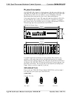
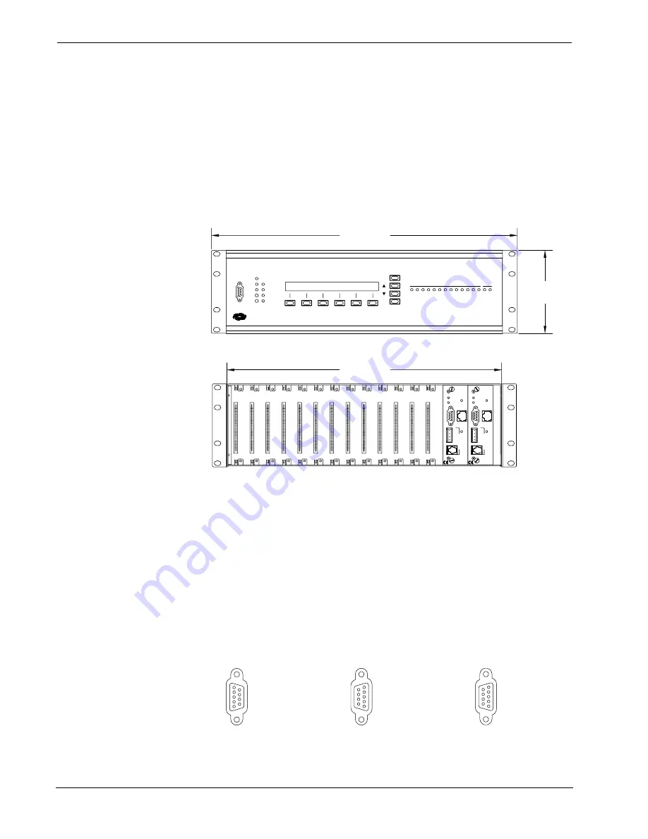
The CNRACKX-DP is housed in a black enclosure with silk-screened labels on the
front panel. On the front panel is a single RS-232 computer port, system status light-
emitting diodes (LEDs), two reset buttons, a reverse LCD display with menu
function and selection buttons, and a row of slot status LED indicators.
The rear panel provides 13 open CNX expansion card slots and the two CNXCPUs.
On each CNXCPU, there are two Cresnet connectors, a single RS-232 computer
port, and two LEDs. The LAN/DPA ports are available when optional
Ethernet Expansion Cards are installed into the CNXCPUs.
CNRACKX-DP Physical Views
5.20 in
(13.21 cm)
Front Panel
Rear View
17.16 in
(43.58 cm)
C
O
M
P
U
T
E
R
6
5
4
3
1
2
7
B
A
13
12
11
10
9
8
19.00 in
(48.26 cm)
CRESTRON
PWR
NET
ERR
HW-R
SW-R
RXD
TXD
LNK
ERR
LAN
P R O F E S S I O N A L C O N T R O L P R O C E S S O R
INTERFACE CONTROL CARD SLOT
MENU
BKLT
CNRACKX-DP
C
R
E
S
N
E
T
LAN
DPA
PROCESSOR
CONTROL
CNXCPU
G
Y
24
Z
CO
M
P
UT
E
R
CRESTRON
PWR
NET
C
R
E
S
N
E
T
LAN
DPA
PROCESSOR
CONTROL
CNXCPU
G
Y
24
Z
CO
M
P
UT
E
R
CRESTRON
PWR
NET
DUAL CPU
CPU
Ten blank faceplates and mounting screws are included. These faceplates are
installed over the empty expansion slots and additional faceplates are available
through Crestron’s Customer Support. Four rubber feet (supplied) can be affixed to
the bottom of the CNRACKX-DP to provide stability and to prevent slippage when
mounted on a flat surface. The unit may also be rack mounted by attaching metal
flanges, known as ears (also supplied), to each end.
CNRACKX-DP Ports
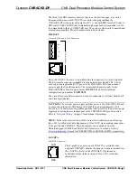
There is only one CNRACKX-DP port, labeled COMPUTER, on the front panel.
The other ports on the rear are part of the CNXCPUs.
COMPUTER
Computer Connectors
Front Panel
CNXCPU-B
C
O
M
P
U
T
E
R
COMPUTE
R
CNXCPU-A
CO
MP
UT
E
R
2
•
CNX Dual Processor Modular Control System: CNRACKX-DP
Operations Guide - DOC. 8151


