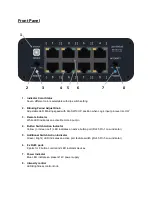


PIN OUT Information
RJ45
PIN 1
– Additional Switch Input (future)
PIN 2
– RED LED
PIN 3 - GND
PIN 4 - +12V
PIN 5
– Switch Logic Control
PIN 6
– Green LED
PIN 7
– Blue LED
PIN 8
– TTL Logic output
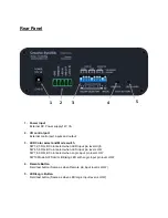
5pin Phonix connector I/O control port
Pin1 : Input GND (System Ground )
Pin2 : Input Remote ( Open/High = Inactive; Low = Active)
Pin3 : Input LED Input ( Default colors: Open/High = Red LED; GND/Low = Green LED )
Pin4 : Switch Out Open collector (Pin4 Logic level changes to LOW when any button is pressed)
Pin5 : Logic Input (Default color: GND/Low = Blue LED, solid or blinking based on Dip SW10)
Note: Input Voltage 0V ~ 2V is considered LOW, 2.1V ~ 12V or open is considered High
TEST Button
Test1: Press “REMOTE”
→
Same as when I/O Pin2 is LOW. RED LED will light up.
DIP SW 1,2,3 combination can change the LED color. RED is the default set.
Test2: Press “REMOTE” and “LED/LOGIC”
→
Same as when I/O Pin2,3 is LOW.
GREEN LED will light up.
DIP SW 4,5,6 combination can change LED color. GREEN is the default set.
Test3: Press ”LED/LOGIC”
→
Same as when I/O Pin5 is LOW. BLUE LED will blink.
DIP SW 7,8,9 combination can change LED color. Blue is the default set.
Period knob can change blinking speed.
DIP SW 10 mode switch position: UP = blinking; DOWN = solid


