background image

12

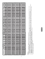
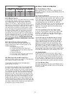
TABLE 1

TEMPERATURE SENSOR ELECTRICAL RATINGS

Volts

Continuous 

Amperes

Inrush 

Amperes

110-120

3.00

30.0

220-240

1.50

15.0

440-480

0.75

7.5

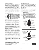
B-4.4) Moisture Sensors:


A normally open (N/O) set of moisture probes are is installed 

in the pump seal chamber, which can be used detect 

any moisture present in the seal chamber and/or motor 

chamber. A 330 K-Ohm, 1 watt test resistor is mounted 

between the probes to allow for verification that the moisture 

sensor circuit is in-tact using a multi-meter. The moisture 

sensors MUST be connected to moisture detector control 

in the control panel. The normally closed (N/C) contact of 

the moisture detector MUST be connected in series with 

the control circuit of the motor contactor. Wiring must be 

provided from the moisture detector sensor probe leads of 

the motor designated W1 and W2. In the event of moisture 

detection, the pump should be pulled and the source of the 

failure located and repaired. 

IF MOISTURE DETECTION 

HAS OCCURRED, SCHEDULE MAINTENANCE AS SOON 

AS POSSIBLE!

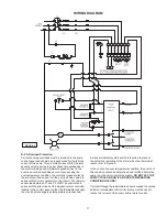
B-4.5) Control Panel and Electrical System:


The control panel and the electrical system MUST be 

properly designed and wired to include at least, but not

limited to the following;


a. Proper grounding per NEC. 


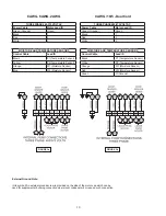
b. A temperature sensing circuit (See Fig. 4) 


c. A moisture detection circuit with continuity test


    circuit  (See Fig. 4) 


d. A level control system. 


e. A main power manual disconnect and lock out. 


f.  A motor starter and overload system.

B-5) When Used with a Variable Speed Drive:

Maximum turndown should not exceed 2:1. Drive should be 

set to operate in constant torque mode. 

It is advisable that all three phase control panels be 

purchased from the factory.

If a panel is to be supplied locally, it is recommended that 

the Crane Pumps & Systems Pump Monitor Relay (P/N 

134667) be used to perform the control circuit functions for 

the Temperature and Moisture Sensor Monitoring described 

in sections B4.3 and B4.4. The Pump Monitor Relay was 

designed to perform these functions in a compact module 

that can be base or panel mounted and is resistant to noise 

issues found with some VFD’s. Indicator lights on the front 

display notify the operator in the event of a fault condition 

for either temperature, moisture or both. Normally open and 

normally closed contacts are flexible to accommodate nearly 

any wiring scenario and the moisture sensor sensitivity can 

be adjusted to prevent nuisance alarms.

SECTION: C START-UP OPERATION

C-1) Check Voltage and Phase:


Before operating pump, compare the voltage and phase 

information stamped on the pump’s identification plate to the 

available power.

C-2) Check Pump Rotation:


Before putting pump into service for the first time, the motor 

rotation must be checked. Improper motor rotation can result 

in poor pump performance and can damage the motor and/

or pump. To check the rotation, suspend the pump freely, 

momentarily apply power and observe the “kickback”. 

“Kickback” should always be in a counter-clockwise direction 

as viewed from the top of the pump motor housing and will 

always be in the opposite direction of the rotation arrows 

cast in the pump volute.

C-2.1) Incorrect Rotation for Three-Phase Pumps:


In the event that the rotation is incorrect for a three-phase 

installation, interchange any two power cable leads at 

the control box. Recheck the “kickback” rotation again by 

momentarily applying power.

C-2.2) Test Procedure For Moisture Sensor Control:


With a moisture detection control, a normally open push 

button is typically provided as a means of checking the 

moisture sensing components. When the push button is 

depressed, the probes will be shorted simulating water. 

While being held, the seal leakage indicating lamp will be 

illuminated to indicate (A) power is supplied to the control, 

(B) the control is operative, and (C) wiring to the moisture 

sensing probes in the pump is intact. This procedure should 

be performed periodically to confirm integrity of the circuit.

C-3) Start-Up Report:


Included at the end of this manual is one start-up report 

sheet, this sheet is to be completed as applicable. Return a 

copy to Crane Pumps & Systems and store the second in 

the control panel or with the pump manual. It is important 

to record this data at initial start-up since it will be useful to 

refer to should servicing the pump be required in the future.

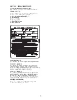
C-3.1) Identification Plate:


Record the numbers from the pump’s identification plate on 

the START-UP REPORT provided at the end of the manual 

for future reference.

Содержание DEMING 7365N-X54-95-30N

Страница 1: ... www cranepumps com Form No 142699 Rev G This product may be covered by one or more of the following patents and other patent s pending US Patent 8 128 360 INSTALLATION and OPERATION MANUAL Solids Handling Submersible Pump 5 Frame 4M Monovane Pumps 75HP 1750RPM 4D Dual Vane Pumps 75 100HP 1750RPM 6V Vortex Pumps 75 100HP 1750RPM 50 75HP 1150RPM 40HP 870RPM 6M Monovane Pumps 75 100HP 1750RPM 6D Dua...

Страница 2: ... TROUBLE SHOOTING 16 RECOMMENDED MINIMUM SUCTION CLEARANCE Fig 9 17 CROSS SECTIONS Fig 8 9 18 EXPLODED VIEW Fig 10 19 PARTS LIST 20 21 WARRANTY 23 RETURNED GOODS POLICY 24 WARRANTY REGISTRATION 24 START UP REPORT 25 26 Other brand and product names are trademarks or registered trademarks of their respective holders Deming is a registered trademark of Crane Pumps Systems Inc 2018 Alteration Rights ...

Страница 3: ...ar eye protection when working on pumps Make sure lifting handles are securely fastened each time before lifting DO NOT operate pump without safety devices in place Always replace safety devices that have been removed during service or repair Secure the pump in its operating position so it can not tip over fall or slide DO NOT exceed manufacturers recommendation for maximum performance as this cou...

Страница 4: ...ephone 937 778 8947 or Crane Pumps Systems Canada in Brampton Ontario 905 457 6223 SECTION B INSTALLATION B 1 Location These self contained pumping units are recommended for use in a sump lift station or basin This pump is designed for submerged continuous duty 15 minutes duty in air at nameplate horsepower pumping sewage effluent wastewater or other nonexplosive or noncorrosive liquids not above ...

Страница 5: ...rd assembly o ring onto the cord assembly as shown in Figure 2 Align the hole in the cord assembly with the alignment pin in the motor cap Lower the cord assembly into the bore of the motor cap taking care to keep the pins aligned Push the cord assembly into the motor housing until fully engaged Install the four 12mm socket head cap scews through the cord assembly into the motor cap Slowly tighten...

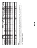
Страница 6: ...N 4DH 13 00 330 75 575 3 60 1750 G 86 7 1 15 96 6 462 4 5 138319 2 4 18 4 2 4 18 4 095 7365N 414 68 30N 4DH 14 57 370 100 460 3 60 1750 E 136 6 1 15 155 3 578 0 5 138319 2 4 18 4 2 4 18 4 070 7365N 414 83 30N 4DH 14 57 370 100 575 3 60 1750 E 109 2 1 15 124 2 462 4 5 138319 2 4 18 4 2 4 18 4 095 7365N 617 67 30N 6MH 13 78 350 75 460 3 60 1750 G 108 4 1 15 120 7 578 0 5 138319 2 4 18 4 2 4 18 4 070...

Страница 7: ... 130 7365N 658 1E 30N 6VT 50 575 3 60 1150 H 61 2 1 15 67 2 320 0 5 138318 6 4 18 4 6 4 18 4 189 7365N 658 96 30N 6VT 60 460 3 60 1150 F 86 7 1 15 96 8 400 0 5 138319 2 4 18 4 2 4 18 4 130 7365N 658 1F 30N 6VT 60 575 3 60 1150 F 69 4 1 15 77 4 320 0 5 138318 6 4 18 4 6 4 18 4 189 7365N 658 67 30N 6VT 13 39 340 75 460 3 60 1150 H 109 3 1 15 119 5 612 0 5 138319 2 4 18 4 2 4 18 4 077 7365N 658 82 30...

Страница 8: ... 0 5 138320 1 0 4 18 4 1 0 4 18 4 049 7365N 850 1G 30N 8T 12 40 315 150 575 3 60 1750 D 159 5 1 0 159 5 640 0 5 138320 1 0 4 18 4 1 0 4 18 4 065 7365N 823 95 30N 8T 13 19 335 50 460 3 60 1150 H 76 4 1 15 84 0 400 0 5 138318 6 4 18 4 6 4 18 4 130 7365N 823 1E 30N 8T 13 19 335 50 575 3 60 1150 H 61 2 1 15 67 2 320 0 5 138318 6 4 18 4 6 4 18 4 189 7365N 823 96 30N 8T 13 78 350 60 460 3 60 1150 F 86 7...

Страница 9: ...1E 30N 10DL 14 76 375 50 575 3 60 1150 H 61 2 1 15 67 2 320 0 5 138318 6 4 18 4 6 4 18 4 189 7365N X52 96 30N 10DL 15 35 390 60 460 3 60 1150 F 86 7 1 15 96 8 400 0 5 138319 2 4 18 4 2 4 18 4 130 7365N X52 1F 30N 10DL 15 35 390 60 575 3 60 1150 F 69 4 1 15 77 4 320 0 5 138318 6 4 18 4 6 4 18 4 189 7365N X52 67 30N 10DL 16 14 410 75 460 3 60 1150 H 109 3 1 15 119 5 612 0 5 138319 2 4 18 4 2 4 18 4 ...

Страница 10: ...symbol An external ground screw is provided on the side of the motor cap which can be used for supplemental bonding connection where local codes permit or require such connection THREE PHASE 460 575 VOLT AC Power Cable Motor Lead ID Green Ground Green Black 1 Red 2 White 3 MOISTURE AND TEMPERATURE SENSORS MOISTURE AND TEMPERATURE SENSORS Control Cable Control Cable Lead ID Lead ID Black P1 Tempera...

Страница 11: ...UST be connected in series with the pilot circuit of the magnetic motor controller located in the control panel so that the thermostat will open the circuit before dangerous temperatures are reached A manual momentary start switch is required to prevent the automatic restarting of the motor when the thermostat resets refer to Figure 4 In the event of an over temperature condition the source of thi...

Страница 12: ...ay notify the operator in the event of a fault condition for either temperature moisture or both Normally open and normally closed contacts are flexible to accommodate nearly any wiring scenario and the moisture sensor sensitivity can be adjusted to prevent nuisance alarms SECTION C START UP OPERATION C 1 Check Voltage and Phase Before operating pump compare the voltage and phase information stamp...

Страница 13: ... using an oil tester with a range to 30 Kilovolts breakdown 3 If oil is found to be clean and uncontaminated measure above 15 KV breakdown refill the seal chamber as per section E 1 2 4 If oil is found to be dirty or contaminated or measures below 15 KV breakdown the pump must be carefully inspected for leaks at the shaft seal before refilling with oil To locate the leak perform a pressure test as...

Страница 14: ...replacing seal remove stationary 4A from mounting plate by prying out with flat screw driver E 3 2 Reassembly Lightly oil DO NOT use grease outer surface of stationary member 4A Press stationary member 4A firmly into mounting plate using a seal pusher aligning seal with pin nothing but the seal pusher is to come in contact with seal face See Fig 6 Make sure the stationary member is in straight and...

Страница 15: ...F 3 MODEL NUMBER This designation consists of numbers and letters which represent the discharge size series horsepower motor phase and voltage speed and pump design This number is used for ordering and obtaining information F 4 SERIAL NUMBER The serial number block will consist of a six digit number which is specific to each pump and may be preceded by an alpha character which indicates the plant ...

Страница 16: ...eller for freedom of operation security and condition Clean impeller and inlet of any obstruction 9 Loosen union slightly to allow trapped air to escape Verify that turn off level of switch is set so that the suction is always flooded Clean vent hole 10 Check rotation If power supply is three phase reverse any two of three power supply leads to ensure proper impeller rotation 11 Repair fixtures as...

Страница 17: ...PTIONAL LIFTING CHAIN TO COLD SHUT FORCE CLOSED AND WELD BAF 6X6 SHOWN SHIM GROUT DIM A DIM B DIM C MODEL NUMBER DIM A INCHES MM 3VC 3 00 76 2 3VR 3VRA 3 50 88 9 3MA 4M 3 75 95 3 4D 4VL 4 00 101 6 4VH 4VHA 4 25 108 4ML 4DM 4MM 4 75 120 7 6V 5 25 133 4 6DL 5 50 139 7 4MB 6 00 152 4 4MH 4MHA 4DH 6ML 6 50 165 1 6MM 6MH 6D 6VT 7 50 190 5 8D 8 75 222 3 8T 9 25 235 8V 11 50 292 1 10DH 12 00 304 8 10DL N...

Страница 18: ...18 FIGURE 9 Vortex Enclosed CROSS SECTIONS FIGURE 10 ...

Страница 19: ...19 EXPLODED VIEWS FIGURE 11 ...

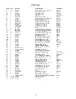
Страница 20: ... 00 Steel 20 1 130073 Ring Retaining 5000 433 S SS 24 2 125856 Sensor Moisture 250 18NPT PP SS 25 1 138175 Block Terminal 9 Pin Male Valox Brass 26 1 138546 Handle Lifting 32FR 304 SS 27 1 127267 Resistor Moisture Sensor 28 1 138545 Pin Dowel 7 16 D 5 8 LG Steel 35 1 138328 XX XXX Stator 32FR 36 1 138327 XX XXX Rotor Assy 32FR RB 37 2 127234B Wire Orange 36 BAR BAR 38 1 138054 Housing Motor 32FR C...

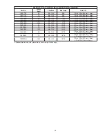
Страница 21: ...6 4 18 4 79 0 1 14in 03in 28 9mm 8mm 138318XL 100 6 4 18 4 79 0 1 14in 03in 28 9mm 8mm 138319XF 50 2 4 18 4 138 0 1 47in 03in 37 3mm 8mm 138319XJ 75 2 4 18 4 138 0 1 47in 03in 37 3mm 8mm 138319XL 100 2 4 18 4 138 0 1 47in 03in 37 3mm 8mm 138320XF 50 0 4 18 5 187 0 1 72in 03in 43 7mm 8mm 47in 02in 12mm 5mm 138320XJ 75 0 4 18 5 187 0 1 72in 03in 43 7mm 8mm 47in 02in 12mm 5mm 1383200XL 100 0 4 18 5 1...

Страница 22: ...22 Notes ...
Страница 23: ... A RETURNED GOODS AUTHORIZATION CONTACT YOUR LOCAL CRANE PUMPS SYSTEMS INC DISTRIBUTOR Products Returned Must Be Cleaned Sanitized Or Decontaminated As Necessary Prior To Shipment To Insure That Employees Will Not Be Exposed To Health Hazards In Handling Said Material All Applicable Laws And Regulations Shall Apply IMPORTANT WARRANTY REGISTRATION Your product is covered by the enclosed Warranty If...

Отзывы: