Crane BARNES 3SF-L Series Скачать руководство пользователя страница 9

9

Pressurize motor housing to 10 P.S.I. Use soap solution 

around the sealed areas and inspect joints for “air bubbles”. 

If,  after  five  minutes,  the  pressure  is  still  holding  constant, 

and no “bubbles” are observed, slowly bleed the pressure 

and remove the gauge assembly. Replace oil as described in 

section F-1.4. If the pressure does not hold, then the leak must 

be located and repaired.

Pumps that have NOT been disassembled, Motor Housing- 

The pressure test may be done with the oil at its normal level.  

Remove pipe plug (39) from motor housing (6). Apply pipe 

sealant to pressure gauge assembly and tighten into hole 

(See Figure 3). Pressurize motor housing to 10 P.S.I. Use soap 

solution around the sealed areas above the oil level and inspect 

joints for “air bubbles”. For sealed areas below the oil level, 

leaks will seep oil. If, after five minutes, the pressure is still 

holding constant, and no “bubbles”/oil seepage is observed, 

slowly bleed the pressure and remove the gauge assembly. If 

the pressure does not hold, then the leak must be located and 

repaired.

CAUTION ! Pressure builds up extremely 

fast, increase pressure by “tapping” air 

nozzle. Too much pressure will damage 

seal. DO NOT exceed 10 P.S.I.

F-1.4)  Replacing Oil:


Motor Housing- 

Set unit upright and refill with new cooling 

oil as per Table 1 (see parts list for amount). Fill to just above 

motor as an air space must remain in the top of the motor 

housing to compensate for oil expansion (see Fig.15). Apply 

pipe thread compound to threads of pipe plug (39) then 

assemble to motor housing (6).

Important ! - For single phase units, oil level 

should be below capacitor

Warning ! - Do not overfill oil. Overfilling of 

motor housing with oil can create excessive 

and dangerous hydraulic pressure which 

can destroy the pump and create a hazard. 

Overfilling oil voids warranty.


TABLE 1 - COOLING OIL - Dielectric

SUPPLIER

GRADE

BP

Enerpar SE100

Conoco

Pale Paraffin 22

Mobile

D.T.E. Oil Light

G & G Oil

Circulating 22

Imperial Oil

Voltesso-35

Shell Canada

Transformer-10

Texaco

Diala-Oil-AX

Woco

Premium 100

F-2) Impeller and Volute Service:

F-2.1) Disassembly and Inspection:

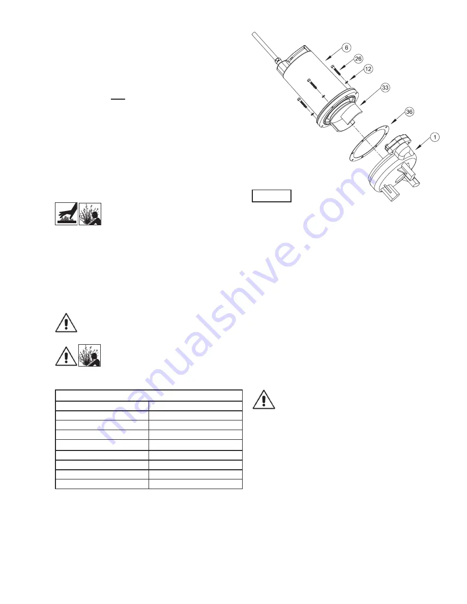
To clean out volute (1) or replace impeller (33), disconnect 

power, remove hex bolts (26), and lockwasher (12), vertically 

lift motor and seal plate assembly from volute (1) see Figure 5. 

Clean out body if necessary. 

Clean and examine impeller (33), for pitting or wear and replace 

if required, inspect gasket (36) and replace if cut or damaged. 

If the impeller (33) needs replacing, place a flat screwdriver in 

the slot of the end of the shaft to hold the shaft stationary while 

unscrewing the jam nut (66) and impeller (33).

F-2.2) Reassembly:

To install impeller (33), clean the threads with thread locking 

compound cleaner. Apply removable Loctite® 603 or equivalent 

to shaft threads. Screw impeller onto the shaft hand tight 

while using a screwdriver in the slot at the end of the shaft 

to hold it stationary. Apply thread locking compound (60) to 

shaft threads. Then install jam nut (66) and torque to 40 ft. 

lbs. It is important that the spring of the lower shaft seal (28) 

seats in the hub of the impeller (33). Rotate impeller to check 

for binding. Position gasket (36) on volute flange and position 

impeller and motor housing on volute (1). Position lockwasher 

(12) on cap screw (26) and screw into volute (1). Torque to 100 

in-lbs. Check for free rotation of motor and impeller.

F-3) Shaft Seal  Service:

Important ! - Handle seal parts with extreme care. 

DO NOT scratch or mar lapped surfaces.

F-3.1) Disassembly and Inspection:

Outer Seal -

 To expose shaft seal (28) for examination, 

disassemble volute and impeller as outlined in paragraph F-

2.1. If further repair is required, remove retaining ring (28d), 

spring (28c) and rotating member (28b) from shaft (see Figures 

6 & 7). Examine all seal parts and especially contact faces. 

Inspect seal for signs of wear such as uneven wear pattern on 

stationary members, chips and scratches on either seal face. 

DO NOT 

interchange seal components, replace the entire 

shaft seal (28). If replacing seal, remove stationary (28a) by 

prying out with flat screwdriver.

FIGURE 5

Содержание BARNES 3SF-L Series

Страница 1: ... Inc constant product improvement program product changes may occur As such Crane Pumps Systems reserves the right to change product without prior written notification 420 Third Street 83 West Drive Bramton Piqua Ohio 45356 Ontario Canada L6T 2J6 Phone 937 778 8947 Phone 905 457 6223 Fax 937 773 7157 Fax 905 457 2650 www cranepumps com Form No 109999 Rev U Series SF 3SF L 5 1 0 HP 1750 RPM 60 Hz ...

Страница 2: ...XPLODED VIEW Fig 16 15 PARTS LIST 16 17 RETURNED GOODS POLICY 12 WARRANTY 18 START UP REPORT 21 22 WARRANTY REGISTRATION SPECIAL TOOLS AND EQUIPMENT INSULATION TESTER MEGGER DIELECTRIC TESTER SEAL TOOL KIT see parts list PRESSURE GAUGE KIT see parts list Other brand and product names are trademarks or registered trademarks of their respective holders Barnes is a registered trademark of Crane Pumps...

Страница 3: ...ert fingers in pump with power connected Always wear eye protection when working on pumps Make sure lifting handles are securely fastened each time before lifting DO NOT operate pump without safety devices in place Always replace safety devices that have been removed during service or repair Secure the pump in its operating position so it can not tip over fall or slide DO NOT exceed manufacturers ...

Страница 4: ... 1750 RPM 60Hz nominal UPPER BEARING Design Single Row Ball Oil Lubricated Load Radial LOWER BEARING Design Single Row Ball Oil Lubricated Load Radial Thrust MOTOR Design NEMA L Single phase Torque Curve Oil Filled Squirrel Cage Induction Insulation Class B Class F on selected models SINGLE PHASE Permanent Split Capacitor PSC Includes overload protection in motor OPTIONAL EQUIPMENT Seal Material I...

Страница 5: ...relief SPEED 1750 RPM 60Hz nominal UPPER BEARING Design Single Row Ball Oil Lubricated Load Radial LOWER BEARING Design Single Row Ball Oil Lubricated Load Radial Thrust MOTOR Design NEMA L Single phase Torque Curve Oil Filled Squirrel Cage Induction Insulation Class B Class F on selected models SINGLE PHASE Permanent Split Capacitor PSC Includes overload protection in motor OPTIONAL EQUIPMENT Sea...

Страница 6: ... is not installed under water for more than one 1 month 2 Immediately upon satisfactory completion of the test the pump is removed thoroughly dried repacked in the original shipping container and placed in a temperature controlled storage area B 4 Service Centers For the location of the nearest Barnes Service Center check your Barnes representative or Crane Pumps Systems Inc Service Department in ...

Страница 7: ...be made in accordance with all applicord electric codes It is recommended that a junction box if used be mounted outside the sump or be of at least Nema 4 EEMAC 4 construction if located within the wet well DO NOT USE THE POWER OR CONTROL CORD TO LIFT PUMP NOTE THE WHITE WIRE IS NOT A NEUTRAL OR GROUND LEAD BUT A POWER CARRYING CONDUCTOR C 4 2 Overload Protection Single Phase The type of in windin...

Страница 8: ...n be expected to operate for years on normal sewage pumping without failing However as with any mechanical piece of equipment a preventive maintenance program is recommended and suggested to include the following checks 1 Inspect motor chamber for oil level and contamination and repair as required per section F 1 2 Inspect impeller and body for excessive build up or clogging and repair as required...

Страница 9: ...Oil Circulating 22 Imperial Oil Voltesso 35 Shell Canada Transformer 10 Texaco Diala Oil AX Woco Premium 100 F 2 Impeller and Volute Service F 2 1 Disassembly and Inspection To clean out volute 1 or replace impeller 33 disconnect power remove hex bolts 26 and lockwasher 12 vertically lift motor and seal plate assembly from volute 1 see Figure 5 Clean out body if necessary Clean and examine impelle...

Страница 10: ...ked or resting on bellows tail Slide retaining ring 28d over shaft and let rest on spring 28c Replace snap ring 32 in groove of shaft Set square ring 27 in groove on outer seal plate 29 and place outer seal plate 29 onto inner seal plate 5 Replacesocketheadcapscrews 64 andtorqueto60in lbs F 4 Motor and Bearing Service F 4 1 Disassembly and Inspection To examine or replace the motor 7 capacitor 9 a...

Страница 11: ...he bearing only until bearing seats against the retaining ring 24 Included with motor Motor Slide lower bearing 25 and motor shaft squarely into the seal plate 5 until bearing seats on the bottom Place stator over rotor lining up motor bolts with holes in seal plate 5 Position capacitor 9 single phase units so that it will lay on the opposite side of the cord entry bosses of the motor housing 6 Re...

Страница 12: ...rmation G 3 MODEL NUMBER This designation consists of numbers and letters which represent the discharge size series horsepower motor phase and voltage speed and pump design This number is used for ordering and obtaining information G 4 SERIAL NUMBER The serial number block will consist of a six digit number which is specific to each pump and may be preceded by a alpha character which indicates the...

Страница 13: ...edom of operation security and condition Clean cutter and inlet of any obstruction 9 Loosen union slightly to allow trapped air to escape Verify that turn off level of switch is set so that the suction is always flooded Clean vent hole 10 Check rotation If power supply is three phase reverse any two of three power supply leads to ensure proper impeller rotation 11 Repair fixtures as required to el...

Страница 14: ...14 FIGURE 15 ...

Страница 15: ...15 FIGURE 16 ...

Страница 16: ...Lg 24 1 085326 Retaining Ring Included with motor 25 1 017414 Bearing 26 4 1 135 1 Cap Screw 5 16 18 x 1 75 Lg Stainless 27 1 027269 Square Ring 28 1 Shaft Seal 005080 Carbon Ceramic Buna N 005080SB Tungsten Tungsten Buna N 005080SD Silicon Carbide Silicon Carbide Buna N STD 005080SF Carbon Ceramic Viton 005080SH Tungsten Tungsten Viton 005080SK Silicon Carbide Silicon Carbide Viton 005080SM Silic...

Страница 17: ...r 2 Discharge 3 8 Stainless 47 2 084948 Socket Head Cap Screw 1 4 20 x 1 25 Lg Stainless 60 A R Loctite 603 65 1 625 02117 Sleeve Fiberglass 66 1 030068 Jam Nut 20 S S TABLE 2 POWER CORD SETS CABLE LENGTH ITEM 16 240 VOLT 1 PHASE includes plug ITEM 16 240 VOLT 1 PHASE no plug 8 FT 103756A 103741A 15 FT STD 103756 103741 20 FT 103756XA 103741XA 30 FT 103756XC 103741XC 50 FT 103756XF 103741XF 75 FT ...

Страница 18: ...TION Your product is covered by a warranty www cranepumps com downloadables CATALOGS_OIPMs Warranty 24MonthWarranty pdf If you have a claim under the provisions of the warranty contact your local Crane Pumps Systems Inc Distributor ...

Отзывы: