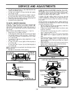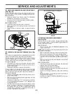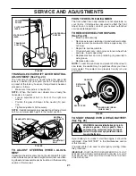
background image

10

OPERATION

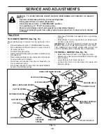
KNOW YOUR TRACTOR

READ THIS OWNER'S MANUAL AND SAFETY RULES BEFORE OPERATING YOUR TRACTOR

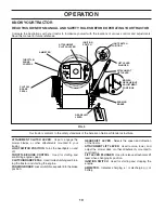
Compare the illustrations with your tractor to familiarize yourself with the locations of various controls and ad just ments.  
Save this manual for future reference.

ATTACHMENT CLUTCH LEVER

:  Used to engage the 

mower blades, or other attachments mounted to your 
tractor.

LIGHT SWITCH POSITION

:  Turns the headlights on and 

off.

THROTTLE/CHOKE CONTROL

:  Used for starting and 

con trol ling engine speed.

CLUTCH/BRAKE PEDAL

:  Used for declutching and brak-

 ing the tractor and starting the engine.

PARKING BRAKE

: Locks clutch/brake pedal into the brake 

position.

GEARSHIFT  LEVER 

- Selects the speed and di rec tion 

of the tractor.

ATTACHMENT LIFT LEVER

:  Used to raise, lower, and 

adjust the mower deck or other attachments mounted to 
your tractor.

LIFT LEVER PLUNGER

:  Used to release attachment lift 

lever when changing its position.  

IGNITION SWITCH

:  Used for starting and stopping the 

engine.

AMMETER

 - Indicates charging (

+

) or discharging (

-

) of 

battery.

Our tractors conform to the safety standards of the American National Standards Institute. 

FIG. 5

PARKING 
BRAKE

CLUTCH/
BRAKE
PEDAL

THROTTLE/
CHOKE
CONTROL

AMMETER

GEAR SHIFT
LEVER

ATTACHMENT 
LIFT LEVER

LIFT LEVER 
PLUNGER

IGNITION
SWITCH

ATTACHMENT 
CLUTCH LEVER

LIGHT SWITCH 
POSITION

MOWER 
DECK HEIGHT 
ADJUSTMENT 
POSITIONS

Содержание Sears 944.603150

Страница 1: ...ad and follow all Safety Rules and Instructions Before Operating This Equipment MODEL NO 944 603150 OWNER S MANUAL Assembly Operation Maintenance Service and Adjustments Repair Parts Sears Canada Inc Toronto Ontario M5B 2B8 02494 00011 SAME AS 944 603151 EXCEPT FOR THE ENGINE ...

Страница 2: ...anges in speed or direction Avoid starting or stopping on a slope If tires lose traction disengage the blades and proceed slowly straight down the slope Safe Operation Practices for Ride On Mowers IMPORTANT THIS CUTTING MACHINE IS CAPABLE OF AMPUTATING HANDS AND FEET AND THROWING OBJECTS FAILURE TO OBSERVE THE FOLLOWING SAFETY INSTRUCTIONS COULD RESULT IN SERIOUS INJURY OR DEATH SAFETY RULES DO NO...

Страница 3: ... and turn machine off if children enter the area Before and when backing look behind and down for small children Mow up and down slopes 15 Max not across Remove obstacles such as rocks tree limbs etc Watchforholes ruts orbumps Uneventerraincouldoverturn the machine Tall grass can hide obstacles Use slow speed Choose a low gear so that you will not have to stop or shift while on the slope Avoid sta...

Страница 4: ...rvice is available by returning the Craftsman Riding Equipment to the nearest Sears Service Centre Department in Canada This warranty applies only while this product is in use in Canada This warranty is in addition to any statutory warranty and does not exclude or limit legal rights you may have but shall run concur rently with applicable provincial legislation Furthermore some provinces do NOT al...

Страница 5: ...eeve Steering Wheel 1 Knob 1 Washer 17 32 x 1 3 16 x 12 Gauge Seat Battery Keys Slope Sheet 2 Hex Bolts 1 4 20 x 3 4 2 Keps Nut 1 4 20 1 Large Flat Washer 1 Hex Bolt 1 4 28 x 1 1 4 1 Locknut 1 4 28 1 Locknut 1 2 20 Steering Wheel Adapter 2 Keys Slope Sheet 1 Oil Drain Tube For Future Use ...

Страница 6: ...VINGTRACTOR FROM SKID ATTACH STEERING WHEEL See Fig 1 ASSEMBLE EXTENSION SHAFT AND BOOT Slide extension shaft onto lower steering shaft Align mounting holes in extension and lower shafts and install 1 4 hex bolt and locknut Tighten securely IMPORTANT TIGHTEN BOLT AND NUT SECURELY TO 10 12 FT LBS TORQUE Place tabs of steering boot over tab slots in dash and push down to secure INSTALL STEERING WHEE...

Страница 7: ...ghten adjustment knob securely FIG 2 SEAT PAN SHOULDER BOLT ADJUSTMENT KNOB FLAT WASHER SEAT FIG 3 FIG 4 HEX BOLT NEGATIVE BLACK CABLE POSITIVE RED CABLE KEPS NUT SEAT PAN TERMINAL COVER DISCARD TERMINAL PROTECTIVE CAPS CONNECT BATTERY See Figs 3 and 4 CAUTION Do not short battery ter minals by allowing a wrench or any other object to contact both terminals at the same time Before connecting batte...

Страница 8: ...lacing motion and mower blade drive belts in the Service and Adjustments section of this manual Verify that the belts are routed correctly CHECK BRAKE SYSTEM Afteryoulearnhowtooperateyourtractor checktoseethat the brake is properly adjusted See TO ADJUST BRAKE in the Service and Adjustments section of this manual NOTE You may now roll or drive your tractor off the skid Follow the appropriate instr...

Страница 9: ...could result in serious injury or death The safety alert symbol is used to identify safety inform ation about hazards which can result in death serious injury and or property damage DANGER indicates a hazard which if not avoided will result in death or serious injury WARNING indicates a hazard which if not avoided could result in death or serious injury CAUTION indicates a hazard which if not avoi...

Страница 10: ...rting the engine PARKINGBRAKE Locksclutch brakepedalintothebrake position GEARSHIFT LEVER Selects the speed and direction of the tractor ATTACHMENT LIFT LEVER Used to raise lower and adjust the mower deck or other attachments mounted to your tractor LIFT LEVER PLUNGER Used to release attachment lift lever when changing its position IGNITION SWITCH Used for starting and stopping the engine AMMETER ...

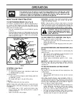
Страница 11: ... parking brake will shut off the engine Depress clutch brake pedal into full BRAKE position and hold Place parking brake lever in ENGAGED position and releasepressurefromclutch brakepedal Pedalshould remain in BRAKE position Make sure parking brake will hold tractor secure BRAKE POSITION PARKING BRAKE DISENGAGED POSITION FIG 6 CLUTCH BRAKE PEDAL DRIVE POSITION STOPPING See Fig 6 MOWER BLADES To st...

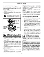
Страница 12: ...fications of the manufacturer of your trac tor Use common sense when towing Too heavy of a load while on a slope is dangerous Tires can lose traction with the ground and cause you to lose control of your tractor BEFORE STARTING THE ENGINE CHECK ENGINE OIL LEVEL The engine in your tractor has been shipped from the factory already filled with summer weight oil Check engine oil with tractor on level ...

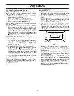
Страница 13: ...perature The attachments can also be used during the engine warm up period NOTE If at a high altitude above 3000 feet or in cold temperatures below 32 F the carburetor fuel mixture may need to be adjusted for best engine performance See TO ADJUST CARBURETOR in the Service and Adjustments section of this manual OPERATION MOWING TIPS Mower should be properly leveled for best mowing per formance See ...

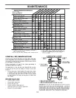
Страница 14: ...il filter 1 2 GENERAL RECOMMENDATIONS The warranty on this tractor does not cover items that have beensubjectedtooperatorabuseornegligence Toreceive full value from the warranty operator must maintain tractor as instructed in this manual Some adjustments will need to be made periodically to properly maintain your tractor All adjustments in the Service and Adjustments section of this manual should ...

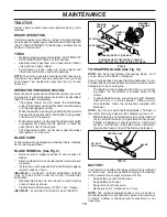
Страница 15: ...g and the attachment clutch is engaged any attempt by the operator to leave the seat should shut off the engine The attachment clutch should never operate unless the operator is in the seat BLADE CARE Forbestresultsmowerbladesmustbekeptsharp Replace bent or damaged blades BLADE REMOVAL See Fig 9 Raise mower to highest position to allow access to blades Remove blade bolt lock washer and flat washer...

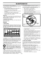
Страница 16: ...NGE SAE VISCOSITY GRADES 20 20 10 10 30 20 20 30 40 0 0 40 80 100 F C 32 60 30 Synthetic 5W 30 10W 30 5W 30 10W 30 C ERTIFIED A M E R I C A N PETOLEUM I N S T I T U T E A P I SERVICE S J C F E N E R GY CONSER V I N G SAE 5W 30 FOR GASOLINE ENGINES Changetheoilafterevery25hoursofoperationoratleastonce a year if the tractor is not used for 25 hours in one year Check the crankcase oil level before st...

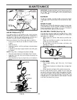
Страница 17: ...under dusty conditions Pull up on air filter cover handle and rotate towards engine Remove cover Carefully remove air filter cartridge and pre cleaner from base Clean base carefully to prevent debris from falling into carburetor NOTE If very dirty or damaged replace cartridge Place new pre cleaner and cartridge firmly in base Align tabs on cover with slots in blower housing and replace cover Hook ...

Страница 18: ...off and push housing guide out of bracket Disconnect anti swaybar from chassis bracket by re moving retainer spring Disconnect suspension arms from rear deck brackets by removing retainer springs Disconnect front links from deck by removing retainer springs Raise lift lever to raise suspension arms Slide mower out from under tractor IMPORTANT IF AN ATTACHMENT OTHER THAN THE MOWER DECK IS TO BE MOU...

Страница 19: ...T E BOTH FRONT LINKS MUST BE EQUAL IN LENGTH TRUNNION D D FIG 19 NUT F FRONT LINKS MANDREL TO LEVEL MOWER HOUSING Adjust the mower while tractor is parked on level ground or driveway Make sure tires are properly inflated See PRODUCT SPECIFICATIONS section of this manual If tires are over or underinflated you will not properly adjust your mower SIDE TO SIDE ADJUSTMENT See Figs 17 and 18 Raise mower...

Страница 20: ...pan keeper Pull belt toward front of tractor and roll around the top groove of engine pulley Install belt through stationary idler and clutching idler Make sure belt is in all pulley grooves and inside all belt guides and keepers Install mower See TO INSTALL MOWER in this sec tion of manual 1 1 2 JAM NUT WITH PARKING BRAKE ENGAGED OPERATING ARM NUT A TO CHECK AND ADJUST BRAKE See Fig 22 Your tract...

Страница 21: ...the tractor rear wheels move freely the transaxle is in neutral Loosen adjustment bolt in front of the right rear wheel Position the gear shift lever in the neutral N posi tion Tighten adjustment bolt securely NOTE Ifadditionalclearanceisneededtogettoadjustment bolt move mower deck height to the lowest position ADJUSTMENT BOLT NEUTRAL LOCK GATE GEARSHIFT LEVER FIG 24 RETAINING RING AXLE COVER FIG ...

Страница 22: ... hood Pull bulb holder out of the hole in the backside of the grill Replace bulb in holder and push bulb holder securely back into the hole in the backside of the grill Close hood INTERLOCKS AND RELAYS Loose or damaged wiring may cause your tractor to run poorly stop running or prevent it from starting Check wiring See electrical wiring diagram in the Repair Parts section TO REPLACE FUSE Replace w...

Страница 23: ... is adjusted properly see above FINAL SETTING Start engine and allow to warm for five minutes Make final adjustments with engine running and shift motion control lever in neutral N position Move throttle control lever to slow position With finger rotate and hold throttle lever against idle speed screw Turn idle speed screw to attain 1750 RPM Whilestillholdingthrottleleveragainstidlespeedscrew turn...

Страница 24: ...AL FUEL SYSTEM PARTS SUCH AS CARBURETOR FUEL FILTER FUEL HOSE OR TANK DURING STORAGE ALSO EXPERIENCE INDICATES THAT ALCOHOL BLENDED FUELS CALLED GASOHOL OR USING ETHANOLORMETHANOL CANATTRACTMOISTUREWHICH LEADSTOSEPARATIONANDFORMATIONOFACIDSDURING STORAGE ACIDIC GAS CAN DAMAGE THE FUEL SYSTEM OF AN ENGINE WHILE IN STORAGE Drain the fuel tank Start the engine and let it run until the fuel lines and ...

Страница 25: ...lty ignition switch 7 Check replace ignition switch 8 Faulty solenoid or starter 8 Check replace solenoid or starter 9 Faulty operator presence switch es 9 Contact an authorized service center department Engine clicks but will not 1 Weak or dead battery 1 Recharge or replace battery start 2 Corroded battery terminals 2 Clean battery terminals 3 Loose or damaged wiring 3 Check all wiring 4 Faulty s...

Страница 26: ... Mower deck not level 4 Level mower deck 5 Low uneven tire air pressure 5 Check tires for proper air pressure 6 Worn bent or loose blade 6 Replace sharpen blade Tighten blade bolt 7 Buildup of grass leaves and trash under mower 7 Clean underside of mower housing 8 Mower drive belt worn 8 Replace mower drive belt 9 Blades improperly installed 9 Reinstall blades sharp edge down 10 Improper blades us...

Страница 27: ...OUR TRACTOR IS EQUIPPED WITH A SPECIAL ALTERNATOR SYSTEM THE LIGHTS ARE NOT CONNECTED TO THE BATTERY BUT HAVE THEIR OWN ELECTRICAL SOURCE BECAUSE OF THIS THE BRIGHTNESS OF THE LIGHTS WILL CHANGE WITH ENGINE SPEED AT IDLE THE LIGHTS WILL DIM AS THE ENGINE IS SPEEDED UP THE LIGHTS WILL BECOME THEIR BRIGHTEST WIRING INSULATED CLIPS NOTE IF WIRING INSULATED CLIPS WERE REMOVED FOR SERVICING OF UNIT THE...

Страница 28: ...28 REPAIR PARTS TRACTOR MODEL NUMBER 944 603150 ELECTRICAL 28 29 26 24 42 43 27 27 25 41 27 27 40 33 90 30 52 D C AMPE RES 45 8 2 1 27 16 16 22 21 ...

Страница 29: ...ttery 6 Ga 11 red 25 146147 Cable Battery 6 Ga w 16 wire red 26 175158 Fuse 20 AMP 27 73510400 Nut Kep Hex 1 4 20 28 4207J Cable Ground 6 Ga 12 black 29 121305X Switch Plunger Nc Gray 30 175566 Switch Ign 33 140403 Key Ign 40 179720 Harness Ign 41 71110408 Bolt Blk Fin Hex 1 4 20unc X 1 2 42 131563 Cover Terminal Red 43 178861 Solenoid 45 121433X Ammeter 52 141940 Protection Wire Loop Hourmeter 90...

Страница 30: ...L NUMBER 944 603150 CHASSIS AND ENCLOSURES 74 10 30 209 31 1 9 209 208 209 5 5 207 144 26 26 60 26 144 26 10 3 3 3 142 3 3 3 142 208 13 208 11 64 143 60 145 37 37 18 14 14 38 38 17 29 28 166 39 212 3 2 206 chassis Laser lt stlt_27 ...

Страница 31: ...1 139976 Bracket Support Fender 37 17490508 Screw Thdrol 6 16 18 x 1 2 TYT 38 175710 Bracket Assembly Pivot 39 174714 Bracket Pivot Laser 60 STD533707 Bolt Rdhd Sqnk 3 8 16unc x 3 4 64 154798 Dash Lower STLT 74 STD541437 Nut Crownlock 3 8 16 UNC 142 175702 Plate Reinforcement STLT 143 154966 Bracket Swaybar Chassis 144 175582 Bracket Pnt Footrest STLT 145 156524 Rod Pivot Chassis Hood 166 171875 S...

Страница 32: ...4 75 78 76 77 1 25 19 24 2 53 35 34 37 36 35 62 36 64 65 59 56 61 55 63 77 22 27 26 6 113 18 51 5 18 6 85 52 30 32 32 30 52 11 85 80 4 3 81 84 82 145 79 16 96 26 26 26 89 90 27 51 48 150 151 202 49 47 50 120 21 8 10 156 165 168 166 163 14 159 161 198 158 164 83 162 169 197 116 70 6 170 212 ...

Страница 33: ...ng Return Clutch 6 75 56 17060620 Screw 3 8 16 X 1 1 4 57 130801 V Belt Ground Drive 59 169691 Keeper Belt Span Ctr 61 17120614 Screw 3 8 16 x 875 62 8883R Cover Pedal Blk Round 63 175410 Engine Pulley LT YT 64 71170764 Bolt Hex 65 STD55143 Washer Lock Hvy Hlcl Spr 7 16 66 154778 Keeper Belt Engine Foolproof 70 134683 Guide Belt Mower Drive RH 74 137057 Spacer Axle 75 121749X Washer 25 32 X 1 1 4 ...

Страница 34: ...RACTOR MODEL NUMBER 944 603150 STEERING ASSEMBLY 44 51 54 5 9 5 7 7 9 4 3 32 43 6 43 8 10 40 11 8 6 9 46 46 8 6 9 2 47 47 26 30 28 1 41 42 37 36 37 38 12 39 68 67 67 67 13 65 85 85 68 15 15 15 29 29 82 88 71 17 29 43 91 ...

Страница 35: ...Washer 13 32 X 7 8 X 16 Ga 29 17060612 Screw 3 8 16 x 3 4 30 STD561210 Pin Cotter 1 8 X 3 4 Cad 32 130465 Rod Tie Wire Form 19 75 Mech 36 155099 Bushing Strg 37 152927 Screw 38 139769 Insert Cap Strg Wh Au 39 19183812 Washer 9 16 x 2 3 8 40 STD541537 Lock nut 41 100711L Adaptor Wheel Strg 42 145054X428 Boot Steering Shaft 43 121749X Washer 25 32 X 1 1 4 X 16 Ga 44 180640 Extension Steering Shaft L...

Страница 36: ...10 182493 Pan Seat 11 166369 Knob Seat 12 121246X Bracket Mounting Switch KEY PART NO NO DESCRIPTION 13 121248X Bushing Snap Blk Nyl 50 Id 14 72050412 Bolt Rdhd Sqnk 1 4 20x1 1 2 15 134300 Spacer Split 28x 96 Yel Zinc 16 121250X Spring Cprsn 1 27 Blk Pnt 17 123976X Nut Lock 1 4 Lge Flg Gr 5 Zinc 21 171852 Bolt Shoulder 5 16 18 Unc 22 STD541431 Nut Hex Lock W Ins 5 16 18 24 19171912 Washer 17 32 X ...

Страница 37: ... Fend STLT Oper 2 184847 Decal Engine 3 184729 Decal Hood LH 4 184728 Decal Hood RH 5 172331 Decal Deck Heavy Duty 6 146046 Decal V Belt Drive Sch 7 181685 Decal Lower Dash 8 170563 Decal Warning 9 184899 Decal Craftsman 10 157140 Decal Fender Danger Eng Fr KEY PART NO NO DESCRIPTION 1 6 2 1 5 8 4 10 3 9 11 7 WHEELS TIRES 11 184730 Decal Side Panel 12 179128 Decal Mower B 42 14 160396 Decal V Belt...

Страница 38: ... 25 Fr 32 140527 Cap Asm Fuel W sym Vented REPAIR PARTS TRACTOR MODEL NUMBER 944 603150 ENGINE 2 1 OPTIONAL EQUIPMENT Spark Arrester 29 44 46 32 31 33 37 33 13 4 72 78 81 3 16 78 23 45 14 38 40 KEY PART NO NO DESCRIPTION 33 123487X Clamp Hose Blk 37 137040 Line Fuel 20 38 181654 Plug Drain Oil Easy 40 124028X Bushing Snap Nyl Blk Fuel Line 44 17670412 Screw Hexwsh Thdrol 1 4 20x3 4 45 17000612 Scr...

Страница 39: ...ft Rh Fixed Length NOTE All component dimensions given in U S inches 1 inch 25 4 mm REPAIR PARTS TRACTOR MODEL NUMBER 944 603150 MOWER LIFT 15 20 16 1718 20 20 15 20 4 5 6 2 3 1 6 5 4 7 8 12 11 31 32 31 32 19 19 13 13 13 13 KEY PART NO NO DESCRIPTION 13 STD624008 Retainer Spring 15 173288 Link Front 16 73350800 Nut Jam Hex 1 2 13 Unc 17 175689 Trunnion Blk Zinc 18 73800800 Nut Lock W Wsh 1 2 13 Un...

Страница 40: ...1 10 9 8 16 68 37 184 30 31 32 33 146 148 145 150 45 144 147 147 142 149 54 52 53 55 56 34 1 46 44 21 24 25 26 27 2 28 29 23 21 21 21 18 18 20 2 48 59 19 4 3 129 92 131 130 92 5 6 21 40 143 36 40 37 40 159 42_D_man t path_stlt_3 142 152 151 153 154 157 158 67 153 156 155 ...

Страница 41: ...1 4 20 x 1 2 159 72140614 Bolt Rdhd Sqn 3 8 16 Unc x 1 3 4 184 19131410 Washer 13 32 x 7 8 x 10 Ga 130794 Mandrel Assembly Includes Hous ing Shaft and shaft Hardware Only Pulley not included 169583 Replacement Mower Complete 1 165892 Mower Deck Assembly 42 2 STD533107 Bolt RDHD SQNK 5 16 18 Unc x 3 4 3 138017 Bracket Assembly Sway Bar Front 4 165460 Bracket Sway Bar 38 42 Deck 5 STD624008 Retainer...

Страница 42: ...42 REPAIR PARTS TRACTOR MODEL NUMBER 944 603150 PEERLESS TRANSAXLE MODEL NUMBER 206 545C ...

Страница 43: ...anged Bushing 5 8 ID 35A 780197 Flanged Bushing 751 36 790075 Brake Disk 37 790007 Brake Pad Plate 38 799021 Brake Pad pkg of 2 39 786026 Dowel Pin 40 792076A Flat Washer 312 ID x 059W KEY PART NO NO DESCRIPTION 41A 790079 Brake Lever 42 792073A Screw 1 4 20 x 1 1 4 42A 792085A Screw 1 4 20 x 2 1 4 43 792075 Locknut 5 16 24 44 790025 Brake Pad Holder 45 786066 Spacer 2625 x 1 0 46 786086 Brake Lev...

Отзывы: