


20
SERVICE AND MAINTENANCE
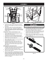
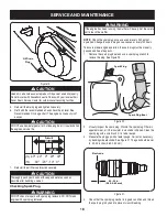
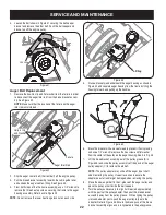
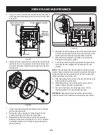
Chute Bracket Adjustment
If the spiral at the bottom of the chute directional control is not fully
engaging with the chute assembly, the chute bracket can be adjusted.
To do so:
1. Loosen the two nuts which secure the chute bracket and reposi-
tion it slightly. See Figure 26.
2. Retighten the nuts.
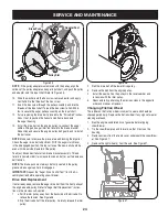
Chute Control
The distance snow is thrown can be adjusted by adjusting the angle of
the chute assembly. Refer to the Operation section for instructions.
The remote chute control cables have been pre-adjusted at the factory.
Move the remote chute lever on the control panel forward to pivot the
upper chute down; move the lever rearward to pivot the upper chute
up.
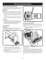
SHAVE PLATE AND SKID SHOES
The shave plate and skid shoes on the bottom of the snow thrower are
subject to wear. They should be checked periodically and replaced
when necessary.
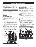
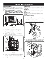
Skid Shoes
NOTE
: The skid shoes on this machine have two wear edges. When
one side wears out, they can be rotated 180° to use the other edge.
1. Remove the six carriage bolts,washers and hex nuts that secure
the two skid shoes to the sides of the auger housing. Refer to
Figure 24.
2. Position the new skid shoes and secure with the carriage bolts
and hex nuts. Make certain the skid shoes are adjusted to be
level.
Shave Plate
1. Remove the carriage bolts, washers and hex nuts which attach
the save plate and the skid shoes to the snowthrower housing.
2. Reassemble new shave plate, making sure heads of carriage
bolts are to the inside of housing. Tighten securely.
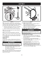
ADJUSTMENTS
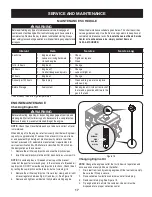
Shift Cable
If the full range of speeds (forward and reverse) cannot be achieved,
refer to the Figure 25 and adjust the shift cable as follows:
1. Place the shift lever in the fastest forward speed position.
2. Loosen the hex nut on the shift cable index bracket. See Fig. 25.
3. Pivot the bracket downward to take up slack in the cable.
4. Retighten the hex nut.
5. If further adjustment is necessary move the shift cable to one of
the alternate holes in the shift cable index bracket.
Figure 24
Figure 25
Figure 26
Содержание C459-52233
Страница 31: ...31 NOTES ...
Страница 35: ...35 NOTES ...
Страница 41: ...41 NOTES ...
Страница 42: ...31 NOTES ...


