background image

Содержание 922210

Страница 1: ... this manual for future reference A CAUTION Read and follow all Safety Rules and Operating Instructions before first use of this product Customer HeEpLine 1 800 932 3188 SAFETY UNPACKING ASSEMBLY USE Sears Roebuck and Co Hoffman Estates IL 60179 USA Visit the Craftsman web page www sears com craftsman 972000 724 8 01 ...

Страница 2: ...essory table of your Craftsman 922811 or 922185 table sew A router mounted on the accessory table will provide expanded capabilities for making rabbets grooves chamfers dovetails and mortise and tenon joints This router mounting kit wi accommodate most Craftsman reuters If used and stored proper y the muter mounting kit will give you years of dep_ndable trouble free perfor mance _1 WARNING Before ...

Страница 3: ...5 16 18 x 3 4 in fiat head 3 Screw 1 4 20 x 1 2 in flat head 4 GUIDE FENCE ASSEMBLY Unplugthe saw A WARNING Unplugthe power supplycord of the saw before mountingthis kit Failure to unplugyour sew couldresult in aooiclental startingcausing possibleseriouspersonal injuw WARNING The saw s motor cord must be disconnected from the receptacJe on saw when using this kit The power cord of the muter must b...

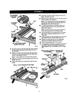
Страница 4: ... the top channel of the rip fence with only one of them between the adjustment screws on the rip fence To install the guide fence brackets align each bracket with two of the t nuts on top of the rip fence See Figure 4 Mote Use the front two t nuts and the back two t nuts leaving the one in the middle empty Secure the guide fence brackets to the rip fence with 5116 in washers and the 5 16 in x 1 2 ...

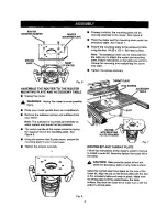
Страница 5: ...ench Remove the subbase screws and subbase from your router Nots The subbase is mounted permanently on some touters and should not be removed The switch handle of the router should be facing the squared end of the mounting plate See Figure 5 Using the screws that fit your router secure the mounting plate to your router base Tighten the screws securely Fig 6 IEWS ACCESSORY ROUTER WITH MOUNTING PLAT...

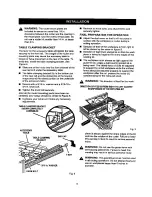
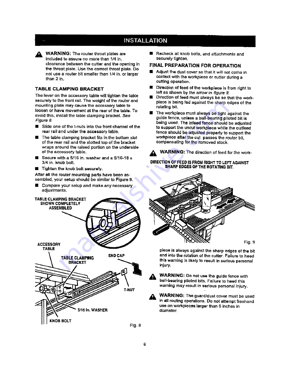
Страница 6: ...HER KNOB BOLT Fig_ 8 Recheck all knob bolts and attachments and seCureLy tighten FINAL PREPARATION FOR OPERATION Adjust the dust cover so that it will not come in contact with the workpiece or cutter during a cuffing operation Direction of feed of the wofkpiece is from right to left as shown by the arrow In figure 9 Direction of feed must always be so that the work piece is being fed against the s...

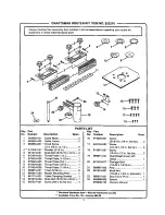
Страница 7: ...6 18 x 1 2 in 4 Throat Plate 1 in 1 19 Throat Plate 1 1 2 in 1 Throat Plate 2 in 1 20 Throat Plate 1 2 in 1 Throat Plate 1 1 8 in 1 21 T Nut 5 16 in 6 22 Router Mounting Plate 1 Table Clamping Bracket 1 23 Knob Bolt 5 16 18 x 3 4 in 1 24 Screw MS x 24 fiat hal 4 Part Number Description Quart 973605 001 Screw 5 16 18 x 3 4 in fiat hd 3 622183 053 Screw 1 4 20 x 1 2 in fiat hd 4 614661 001 Screw 10 ...

Страница 8: ...ies and owner s manuals that you need to do it yourself call Sears PartsDirectSM 1 800 366 PART 6a m 11p m CST 1 800 366 7278 7 days a week www sears com partsdirect To purchase or inquire about a Sears Service Agreement 1 800 827 6655 7 a m 5 p m CST Mon Sat Para pedir servicio de reparacibn a domicilio y para ordenar piezas con ontrega a dornicilio 1 888 SU HOGAR _ 1 888 784 6427 Au Canada pour ...

Отзывы: