background image

Содержание 917.259547

Страница 1: ...ities o Service and Adjustments Repair Parts For answers to your questions about this product Call 1 800 659 5917 Sears Craftsman Help Line 5 am o5 pm Mon Sat CAUTION Read and follow all safety rules and instructions before operating this equipment mUlllllllllll IIII III II ...

Страница 2: ...mower could suddenly turn over if a wheel is over the edge of a cliff or ditch or if an edge caves in Do not mow on wet grass Reduced traction could cause sliding_ Do not tryto stabilize the machine by puttingyour foot on the ground Do not use grass catcher on steep slopes 2 11 CHILDREN Tragic accidents can occur if the operator is not alert to the presence of children Children are often attracted...

Страница 3: ...ective working order by the operator In the state of California the above is required by law Section 4442 of the California Public Resources Code Other states may have similar laws Federal laws apply on federal lands A spark arrester for the muffler is available through your nearest Sears Authorized Service Center Department See REPAIR PARTS section of this manuai o _1_ III II IIIIIIl_l_lu_l_lj l_...

Страница 4: ...ne 18 Oil Change 17 Oil Level 13 17 Oil Type 17 Preparation 13 Repair Parts 48 53 Starting 14 Storage 26 F Filters Air 18 Fuel 19 Fuel Type 13 Storage 26 Fuse 24 G Gauge Wheels 8 H Hood Remova Installation 24 L Leveling Mower Deck 2t LubricationChart 15 M Maintenance Schedule 15 Mower Adjustment Front4o Back 21 Adjustment Side to Side 21 Blade Sharpening 16 Blade Replacement 16 Cutting Height 12 I...

Страница 5: ...mulch discharge or bag clippings bagger optional without changing blades For models not equipped as 3 in 1 Convertible mowers See MOWER in the Repair Parts section of this manual RAMP TOPS AND FEET let you load and unload tractor from a pickup truck Use with 2 x 8 or 2 x 10 lumber ROLLER for smoother lawn surface 36 inch wide 18 inch diameterwater tight drum holds upto 390 lbso of weighL Rounded e...

Страница 6: ...her x 1 3 16 x 12 Gauge 1 Lock Washer 1 2 lllllllllllltilllllllH 2 Hex Bolts1 4 20 X 3 4 2 Hex Nuts 9 32 x 5 8 x 16 Gauge f2 Lock Washers 1 4 Seat Steering Boot Mulcher Plate Steering Wheel Video Cassette t Manual Parts Bag i i iiii ll i i Parts bag contents not shown full size 2 Shoulder Bolts Steering Wheel Adapter 2 Washers 3 8 x 7 8 x 14 Gauge 2 Gauge Wheels E _ 2 Center lock Nuts 2 Latch Hook...

Страница 7: ...ten sion Position steering wheel so cross bars are horizontal left to right and slide inside boot and onto adapter Assemble large flat washer 3 8 lockwasher 3 8 hex bolt and tighten securely Snap steering wheel insert into center of steering wheel Remove protective materials from tractor hood and grill IMPORTANT CHECK FOR AND REMOVE ANY STAPLES IN SKID THAT MAY PUNCTURE TIRES WHERETRACTOR IS TO RO...

Страница 8: ...ressure is important for best cutting performance Reduce tire pressure to PSI shown in PRODUCT SPECIFICATIONS on page 3 of this manual CHECK DECK LEVELNESS For best cutting results mower housing should be properly leveled See TO LEVEL MOWER HOUSING in the Service and Adjustments section of this manual CHECK FOR PROPER POSITION OF ALL BELTS See the figures that are shown for replacing motion and mo...

Страница 9: ...Battery is properly prepared and charged Minimum 1 hour at 6 amps Seat is adjusted comfortably and tightened securely All tires are properly inflated For shipping purposes the tires were ovennflated at the factory Be sure mower deck is properly leveled side to side front to rear for best cutting results Tires must be properly inflated for leveling Check mower and drive belts Be sure they are route...

Страница 10: ... WARNING FORWARD FAST SLOW CLUTCH LIGHTS ON ENGINE ON ENGINE OFF OIL PRESSURE OVER TEMP LIGHT I I FUEL CHOKE MOWER HEIGHT DIFFERENTIAL PARKING BRAKE LOCK LOCKED UNLOCKED N H L REVERSE NEUTRAL HIGH LOW PARKING BRAKE MOWER LIFT ATTACHMENT CLUTCH ENGAGED ATTACHMENT CLUTCH DISENGAGED IGNITION DANGER KEEP HANDS AND FEET AWAY HYDROSTATIC FREE WHEEL Hydro Models only 10 ...

Страница 11: ...ational Standards Institute ATTACHMENT CLUTCH LEVER Used to engage the mower blades or other attachments mounted to your tractor LIGHT SWITCH Turns the headlights on and off THROTTLE CHOKE CONTROL Used to control engine speed CLUTCHtBRAKE PEDAL Used for declutching and brak ing the tractor and starting the engine PARKING BRAKE Locks clutch brake pedal into the brake position GEAR SHIFT LEVER Selec...

Страница 12: ...tanding idlewith the engine running hot engine exhaust gases may cause browning of grass To eliminate this possibility always stop engine when stopping tractor on grass areas l CAUTION Always stop tractor com pletely as described above before leav ing the operator s position to empty grass catcher etc t TO USE THRO3 rLE CONTROL See Fig 9 Always operate engine at full throttle Operating engine at l...

Страница 13: ...NE OIL LEVEL See Fig 17 The engine inyour tractor has been shipped from the factory already filled with summer weight oil Check engine oil with tractor on level ground o Unthread and remove oil fill cap dipstick wipe oil off Reinsert the dipstick into the tube and rest oil fill cap on the tube Do not thread the cap onto the tube Remove and read oil level If necessary add oil until FULL mark on dip...

Страница 14: ...result in a more even distribution of clippings and more uniform cutting When mowing large areas start by turning to the right so that clippings will discharge away from shrubs fences driveways etc_ After one or two rounds mow in the opposite direction making left hand turns until finished See Fig 11A tf grass is extremely tall it should be mowed twice to reduce load and possible fire hazard from ...

Страница 15: ...lbs maximum Do not ovedighten GENERAL RECOMMENDATIONS The warranty on this tractor does not cover itemsthat have been subjected to operator abuse or negligence To receive full value from the warranty operator must maintain tractor as instructed in this manual Some adjustments will need to be made periodically to properly maintain your tractor All adjustments in the Service and Adjustments section ...

Страница 16: ... UNES ON THEBOLTHEAD TO SHARPEN BLADE See Fig 14 Care should be aken to keep the blade balanced_ An unbalancedblade willcause excessive vibrationand even tual damage to mower and engine The blade can be sharpened witha file oron a grinding wheel Do not attempt to sharpen while onthe mower To check blade balance you willneed a 5 8 diameter steel bolt pin oracone balancer When using a cone balancer ...

Страница 17: ...on_ Tighten oil fiU cap dipstick securely each time you check the oil level n _ _l m mmn iml mi _ Im IBmLITHES TO CHANGE ENGINE OIL See Figs 15 and 16 Determinetemperature range expected before oilchanger All oi must meet API service classificationSF SG or SH_ o Be sure tractor is on level sufface_ Oil will drain more freely when warm Catch oil in a suitable container Remove oilfill cap dipstick B...

Страница 18: ...ace a dirty bent or damaged cartridge_ NOTE Do notwash the paper cartridge or use pressurized air as this will damage the cartridge Reinstall the pre cleaner cleaned and oiled over the paper cartridge Reassemble air cleaner wing nut cover and tighten knob securely To insure proper cooling make sure the grass screen cooling fins and other external surfaces of the engine are kept clean at all times ...

Страница 19: ... and check for oil leaks Correct any leaks before placing engine intofull operation_ OIL FILTER llr_lllH l_lllll _ i i IN LINE FUEL FILTER See Fig 18 The fuelfilter should be replaced once each season if fuel filter becomes clogged obstructingfuel flow to carburetor replacement is required With engine cool remove _ter and plug fuel line sections Place new fuel filter in position in fuel line with ...

Страница 20: ...f engine pulley Disconnect clutch rod from clutch lever by removing retainer spring Disconnect anti sway bar from chassis bracket by removing retainer spring Disconnect suspension arms from rear deck brackets by removing retainer springs Disconnect front links from deck by removing retainer springs Raise lift lever to raise suspension arms Slide mower out from under tractor IMPORTANT IF AN ATTACHM...

Страница 21: ...TO SIDE IF THE FOLLOWING FRONT TO BACK ADJUSTMENT IS NECESSARY BE SURE TO ADJUST BOTH FRONT LINKS EQUALLY SO MOWER WILL STAY LEVEL SIDE TO SIDE To obtain the best cutting results the mower housing should be adjusted so that the front is approximately 1 8 to 1 2 lower than the rear when the mower is in its highest position Check adjustment on right side of tractor Measure dis tance D directly infro...

Страница 22: ...ng arm and nut A on brake rod If distance is other than 1 1 2 loosen jam nut and turn nut A until distance becomes 1 1 2 Retighten jam nut against nut WL Road test tractor for proper stopping distance as stated above Readjust if necessary If stopping distance is still greater than six 6 feet in highest gear further maintenance is necessary Contact your nearest au thorized service centeddepartmenL ...

Страница 23: ...ossbars are not horizontal left to fight when wheels are positioned straightforward remove steer ing wheel and reassemble per instructions inthe Assembly section of this manual FRONT WHEEL TOE IN CAMBER The front wheel toe in and camber are not adjustable on your tractor If damage has occurred to affect the front wheel toe in or camber contact your nearest authorized service centeridepartmento TO ...

Страница 24: ...rd engine and lift off of tractor To replace reverse above procedures CHARGED POSITIVE NEGA_VE TERMINAL TERMINAL FIG 30 TO REPLACE HEADLIGHT BULB Raise hood Pul bulb holder out of the hole in the backside of the grill Replace bulb in holder and push bulb holder securely back into the hole in the backside of the gdlL Close hood INTERLOCKS AND RELAYS Loose or damaged wiring may cause your tractor to...

Страница 25: ...cap which allows some adjustment within the limits allowed by the cap Do not attempt to remove the limiter cap The limiter cap cannot be removed without breaking the adjusting needler o Be sure you have a clean air filter and the throttle control cable is adjusted properly see above Start engine and allow to warm for five minutes Make adjustmentswith engine running andshift motion control lever in...

Страница 26: ...S IMPORTANT TO PREVENT GUM DEPOSITS FROM FORMING IN ESSENTIAL FUEL SYSTEM PARTS SUCH AS CARBURETOR FUEL FILTER FUEL HOSE OR TANK DURING STORAGE ALSO EXPERIENCE INDICATES THAT ALCOHOL BLENDED FUELS CALLED GASOHOL OR USING ETHANOL OR METHANOL CAN ATTRACT MOISTURE WHICH LEADS TO SEPARATION AND FORMATION OF ACIDS DURING STORAGE ACIDIC GAS CAN DAMAGE THE FUEL SYSTEM OF AN ENGINE WHILE IN STORAGE Drain ...

Страница 27: ......

Страница 28: ...ir pressure_ 6 Wom bent or toose blade 7 Buildup of grass leaves and trash under mower 8 Mower drive belt worn 9 Blades improperly instaUed 10 Improper blades used 11_ Clogged mower deck vent holes from buildup of grass leaves and trash around mandrels 1 Switch is OFF 2 Bulb s burned out 3 Faulty light switch 4 Loose or damaged wiring 5 Blown fuse 1 Bad battery cetl s o 2 Poor cable connections 3 ...

Страница 29: ... NOT CONNECTED TO THE BATTERY BUT HAVE THEIR OWN ELECTRICAL SOURCE BECAUSE OF THIS THE BRIGHTNESS OF THE LIGHTS WILL CHANGE WITH ENGINE SPEED AT IDLE THE LIGHTS WILL DIM AS THE ENGINE IS BROWN z l 30 J RELAY 28 VOLTS AC MIN 3600 RPM CHARGING SYSTEM DISCONNECTED SPEEDED UP THE LIGHTS CONNECTIONS WILL BECOME THEIR BRIGHTEST HEADLIGHTS O REMOVABLE CONNECTIONS NON REMOVABLE WIRING INSULATED CLIPS NOTE...

Страница 30: ...REPAIR PARTS TRACTOR MODEL NUMBER 917 259547 ELECTRICAL 41 26 l I 1 I t I I I I I 16 16 I I 1 3O ...

Страница 31: ...t 24 4799J Cable Battery 6 Gauge Red 11 25 146147 Cable Battery 6 W 16 Gauge Red Wire 26 108824X Fuse 30 Amp 28 4207J Cable Ground 6 Gauge Black 12 29 160784 Switch Plunger 30 14030 1 Switch Ignition 31 124211X Nut Ignition 32 141226 Cover Key Switch 33 1093IOX Key Ignition 40 161352 Harness ignition 41 7i 110408 Bolt Hex Head Fin I 4 20 x 1 2 42 131563 Cover Terminal Red 43 145673 Solenoid 44 736...

Страница 32: ...REPAIR PARTS TRACTOR MODEL NUMBER 917 259547 CHASSIS AND ENCLOSURES 29 28 58 12 31 14 11_ 4 37 53 54 3 74 3 38_ 39 14 32 ...

Страница 33: ...ash Bolt Carriage 3 8 16 x 1 Panel Dash LH Clip Ttnnerman GrilJe P L Panel Dash RH Screw Thdo Roll 3 8 16 x 1 2 Hood Assembly Bumber Hood Washer 13 32 x 13 16 x 12 Gauge Locknut Grille w Clips MS 558 Lens Grille FendedFootrest Pnt STLT N Hold 558 Bracket Fender Support Screw Thdrol 5 16 18 x 1 2 Tyt Pivot Bracket Assembly LH Pivot Bracket Assembly RH Nut Lock w Insert 1 4 20 UNC Washer 9 32 x 7 8 ...

Страница 34: ...REPAIR PARTS TRACTOR MODEL NUMBER 917 259547 DRIVE 57 31 88 87 86 81 _82 87 21 88 58 18 5 51 5 6 19 6 62 61 56 18 35 34 29 65 64 37 1 72 116 27 121 i 48 118 26 51 53 i 26 27 34 ...

Страница 35: ...Assembly Foot Pedal 85 150360 35 t20183X Bearing Nylon 86 71208 36 STD551062 Washer 87 19212016 37 STD57 810 Roll Pin 88 12000008 38 123674X Pulley Idler Flat 89 154886 39 STD523727 Bolt 90 124346X 40 4470J Spacer Split 395x _59 112 19091210 4t 154777 Keeper Belt ldlerFoot Proof 1t6 72110610 42 19131312 Washer 13 32 x 13 16 x 12 Gauge 118 154774 47 127783 Pulley Idler V Groove Plastic 121 154419 4...

Страница 36: ...REPAIR PARTS TRACTOR MODEL NUMBER 917 259547 STEERING ASSEMBLY 37 46 67 9__6a 70 13 6 47 15 tJ 32 28 3O 36 ...

Страница 37: ...ed Stamped Washer Lock Hvy Hlcl Spr 3 8 Bearing Axle STLT GT Locknut Flange 5 8 11 UNC Shaft Asm Strg Private Label Washer Thrust 515 x 750 x 033 Support Shaft Washer Shim 1 4 x 5 8 x 062 Screw Hex Socket 1 4 20 x 5 8 Shaft Asm Pittman Bracket Steering Bushing Rod Tie BIk Lt Gear Sector Washer 13 32 x 7 8 x 16ga Screw Thdrol 3 8 16x3 4 Ty tt Pin Cotter 1 8 x 3 4 Cad Rod Tie Wire Form 19 75 Mech Bu...

Страница 38: ...at Screw Thd Roll 3 8 16 x 1 Washer 13 32 x 1 x 14 Gauge Pan Seat Emboss QCK Conn Bracket Switch Mounting Bushing Snap Bolt Carriage 1 4 20 x 1 1 2 KEY PART NO NO DESCRIPTION 15 134300 16 121250X 17 123976X 21 153236 22 STD541431 23 7478O814 24 19171912 25 127018X 26 STD551150 Spacer Split 28 x 88 Spring _ de Locknut Flange 1 4 Gra 5 Bolt Shoulder 5 16 18 UNC Nut Bolt Hex Head Fin 1 2 13 x 7 8 Gra...

Страница 39: ...4516 16175O 161751 DESCRIPTION Decal Chassis 6 Speed 42 Decal V Belt Schematic Decal Battery Dngr Psn Eng Decal Battery Diehard Sears Decal Lift Handle Pad Footrest LH STLT Pad Footrest RH STLT Owner s Manual English Owner s Manual Spanish WHEELS TIRES 5 8 4 10 11 39 KEY PART NO NO 1 59192 2 65139 3 106222X 4 59904 5 106732X427 6 278H 7 9040H 8 106108X427 9 138468 10 7152J 11 104757X 144334 DESCRI...

Страница 40: ... _ _ i_ _ _ _ ...

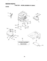
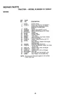
Страница 41: ...x5 8 T Engine See Breakdown Kohler Model No CV15S 41567 Muffler Nipple Pipe 3 8 NPT x 3 1 2 Elbow Std 90 Degree 3 8 18 Npt Washer Shield Heat Arrestor Spark Tank Fuel Cap Assembly Fuel Tank Vented Clamp Hose BIk Screw Thdrol 5 16 18 x 3 4 TYT Line Fuel Plug Oil Drain Order From Engine Manufacturer Bushing Snap Fuel Line Screw Hex Washer Head Thd Roll t 4_20 x 3 4 Washer 9 32 x 7 8 x 16 Gauge Washe...

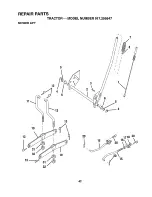
Страница 42: ...REPAIR PARTS TRACTOR MODEL NUMBER 917 259547 MOWER LIFT 7 11 5 3 13 6 13 I 19 I 20 15 20 718 20 15 42 ...

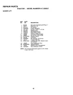
Страница 43: ... 73540600 Wire Asm Inner Spring W Plngr LT Shaft Asmo Lift Pin Groove E Ring 5133 62 Washer 21 32 x 1 x 21 Ga Bearing Nylon Grip Handle Fluted Button Plunger Red Link Lift Lh Fixed Length Link Lift Rh Fixed Length Retainer Spring Link Front Nut Jam Hex 1 2 13 Uric Trunnion BIk Zinc LockNut Hex with Washer Insert t 2 13 UNC Arm Suspension Rear Retainer Spring Bearing Pivot Lift Spherical Nut Crown ...

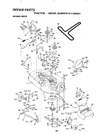
Страница 44: ...REPAIR PARTS TRACTOR MODEL NUMBER 917 259547 MOWER DECK 76 17 68 34 33 32 31 102 105 106 2 16 18 29 21 22 _23 24 28 27 ...

Страница 45: ... Pivot with Nibs 130 Rod Clutch Secondary with Nibs 131 Guard Mandrel L H 132 Retainer Screw Thd Roll 1 4 20 x 5 8 141 Washer Hardened Roller Assembly Cam Follower Bolt Shoulder t0 24 Grade 5 Locknut Bolt Shoulder 5 16 18 UNC Arm Assembly Pad Brake Washer Hardened Arm Idler Spacer Retainer NOTE 140086 141043 149846 144200 142427 13187O 127847 21748X 12000029 128903 127845 154809 127498 153701 STD5...

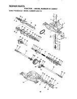
Страница 46: ...REPAIR PARTS TRACTOR MODEL NUMBER 917 259547 DANA TRANSAXLE MODEL NUMBER 4360 122 9 27 20 2t 36 22 24 31 25 t0 11 53 54 47 4B 9 _9 62 46 ...

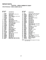
Страница 47: ...160949 24 143673 Shaft Intermediate 60 160950 25 2244J Key Woodruff No 61 61 160951 26 105916X Ring Retaining 62 120961X 27 t20470X Sprocket t8T 63 7294J 28 110070X Spacer 1_131X 1 45X 494 64 08989X 29 142677 Gear Spur 37T 65 t60952 30 142681 Gear Spur 35T 66 120954X 31 124644X Gear Spur 30T 67 t60953 32 08980X Gear Spur 25T 68 138244 33 t20406X Gear Spur 22T 69 108996X 34 34796 Gear Spur t9T 70 1...

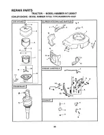
Страница 48: ...ACTOR MODEL NUMBER 917 259547 KOHLER ENGINE MODEL NUMBER CV15S TYPE NUMBER PS 41567 AIR INTAKE 12 __4 _5 6_o 8_ I i _9 CRANKSHAFT 1 2 _ _ _ I j i BLOWER HOUSING AND BAFFLES 15 _4 t4 9 1 r z_ ls tLt lO r 0 16 13 6 8 48 ...

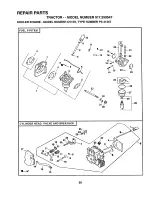
Страница 49: ...Mounting 3 11 M 0545020 Screw Hex Flange M5 x 8 x 20 3 12 12 063 05 Baffle Intake Side 13 M 0645016 Screw Hex Flange M6 x to0 x 16 2 14 12 063 08 Baffle Cylinder Head 15 12 063 01 Baffle Cylinder NOT ILLUSTRATED 12q 13 64 Decal Horsepower 12 079 07 12 237 01 M 0664020 M 0545016 12 536 09 M 0443020 SM 0443025 12 089 11 12 089 23 12 089 24 M 0641060 SM 0642025 13 12 090 05 14 25 158 tl 15 12 079 01 ...

Страница 50: ...REPAIR PARTS TRACTOR MODEL NUMBER 917 259547 KOHLER ENGINE MODEL NUMBER CV15S TYPE NUMBER PS 41567 2 33 19 _ 21 14 23 32 31 3O 28 CYLINDER HEAD VALVE AND BREATHER i 19 18 22 21 20 12 13 27 50 ...

Страница 51: ...32 05 22 t2 089 10 Spring Choke 20 M 0640034 23 t2 146 02 Plate Choke 21 24 194 01 24 t2 337 03 Jet Main 22 24 186 03 25 12 757 02 Kit Float 23 M 0545010 26 12 04t 05 Gasket Bowl 27 12 I04 01 Bowl Fuel 24 12 0 8 01 28 12 757 09 Kit Solenoid Assembly 25 12 402 02 includes Key Number 29 26 12 318 09 29 2 041 06 Gasket Bowl Retainer Screw 27 X 75 23 30 M 0641060 Nut Hex Flange M6 x 1 0 2 31 X 25 63 W...

Страница 52: ...REPAIR PARTS TRACTOR MODEL NUMBER 917 259547 KOHLER ENGINE MODEL NUMBER CV15S TYPE NUMBER PS 41567 IGNITION ELECTRICAL 17 11 _10 13 __ OIL PAN LUBRICATION I 23 22 2 8 9 0 1 2 52 ...

Страница 53: ...045 Dipstick Assembly Includes Key Numbers 2 and 3 Kit Oil Fill Cap Includes Key 3 O Ring Dipstick O Ring Upp erOil Fil Tube Tube Oil Fftl Screw Hex Flange M5 x 0 8 x 20 O Ring Lower Oil Fill Tube Screen Oil Pick up Cover Oil Pick up Screen Screw Hex Flange M5 x 0 8 x 16 Screw Hex Flange MIO x 1 5 x 25 Bracket Oil Pump Relief Valve Spring Oil Pump Relief Valve P_ston Oi_Pump Relief Valve Body Oil ...

Страница 54: ...54 ...
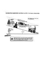
Страница 55: ...D HOLD THIS LEVEL WITH SKY LINE OR TREE 15 MAX i1 11111111 iiiii iiiiiii i iiiiiiii1 111 HII l llllll _ Operate your Tractor up and down the face of slopes not I _ _ greater than 15 never across the face Make turns gradu _ _ ally to prevent tipping or loss of control Exercise extreme i ll caution when changing direction on slopes i ...

Страница 56: ... model plate located under the seat The model number for your engine will be found on the blower housing of the engine All parts listed herein may be ordered from any Sears Roebuck and Co Service Center Department and most Re tail Stores_ WHEN ORDERING REPAIR PARTS ALWAYS GIVE THE FOLLOWING INFORMATION PRODUCT TRACTOR MODEL NUMBER 917 259547 ENGINE MODEL NO CV15S TYPE NO PS 41567 PART NUMBER PAR3 ...

Отзывы: