background image

Содержание 390.253251

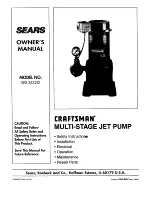
Страница 1: ...ing Instructions BeforeFirstUse of This Product Save ThisManual For Future Reference CRRFTSMRN MULTI STAGE JET PUMP Safety Instructior_ Installation Electrical Operation Maintenance Repair Parts Sears Roebuck and Co Hoffman Estates IL 60179 U S A PRINTED IN U S A Form No F642 9807 Rev 716 98 ...

Страница 2: ...ed to hazards 1 To avoid risk of serious bodily injury and property damage read safety instructions carefully before in stalling pump 2 Follow local and or national plumbing and electri cal codes when installing pump 3 Keep well covered while installing pump to prevent leaves and other debris from falling into well con taminating well and possibly damaging pump 4 Protect pump and piping system fro...

Страница 3: ...nk drops to 40 pounds per square inch PSI and stops the pump when the tank pressure reaches 60 PSI Adapter Flange The VMS pump is equipped with an adapter flange This adapter facilitates installation and removal of the pump without disturbing piping See Pages 6 and 7 for more information Pressure Relief Valve Under certain conditions VMS pumps can generate very high pressure The pressure relief va...

Страница 4: ... 8 6 7 8 Pumping Depth In Feet 1_ 110 120 140 1_ 1_ 210 6 5 5 0 5 0 5 0 4 2 3 5 2 0 5 5 4 8 4 8 4 7 3 9 2 7 1 5 7 8 6 4 5 1 5 0 4 5 4 0 3 2 2 1 6 6 5 4 4 7 4 6 4 2 3 4 2 6 1 7 7 8 6 4 5 1 5 0 4 5 4 0 3 2 2 1 6 6 5 4 4 7 4 6 4 2 3 4 2 6 1 7 Use 160 PSI Min Rating Plastic Pipe Jet Package No 29670 2 Single Pipe use 1 1 4 galvanized pipe Jet Package No 29902 3 S_ingle Pipe use 1 1 4 galvanized pipe J...

Страница 5: ...ssible use as few elbows and fittings as possible 2 Be sure well is clear of sand Sand will plug the pump and void the warranty 3 Protect pump and all piping from freezing Freezing will split pipe damage pump and void the warranty Check locally for frost protection requirements usually pipe must by 12 below frost line and pump must be insulated 4 Be sure all pipes and foot valve are clean and in g...

Страница 6: ...ith a close nipple Use Teflon tape on male threads 4 Install nozzle and venturi in deep well ejector 5 Using Teflon tape on male threads install special plastic pipe adapter supplied with ejector by screwing adapter into 1 1 4 tapped hole in ejector body see Figures 6 and 8 above 6 Thread a 1 plastic pipe adapter or a 1 nipple into the 1 tapped hole in ejector body see Figure 8 7 Install sufficien...

Страница 7: ...s will help prime the system and also serves as a check on leaks which may occur in the piping and foot valve as the piping is assembled Single Pipe Ejector Installation Single pipe installations require see Figure 9 Pipe Clamp L Figure I 0A Use tripod and lever hoist to lower pipe into the well Figure 10B Pipe clamp detail a Galvanized steel suction pipe b Leather packer type ejector with built i...

Страница 8: ... 1 If increasing discharge pipe size install reducer in pump discharge port Do not increase pipe size by stages 2 When the pump is set away from the points of water use the discharge pipe size should be in creased to reduce pressure losses caused by fric tion Upto 100 ft run 1 100 ft to 300 ft run 1 1 4 300 ft to 600 ft run 1 1 2 Pressure Tank Installation Deep Well The Pressure Tank provides a re...

Страница 9: ...w 31870398 Figure 14 Motor wiring connections through Pressure Switch Match motor voltage to line voltage IAWARNINGI Hazardous voltage Can shock burn or kill Connect ground wire before connecting power supply wires Use the wire size induding the ground wire specified in the wiring chart If possible connect the pump to a separate branch cir cuit with no other appliances on it J A WARNING JExplosion...

Страница 10: ... No 1 two or three times to re move entrapped air from the suction pipes 3 If pressure does not build up after priming pump several times check the following a Suction pipe in the water b Suction pipe has no leaks NOTICE Air can leak in even where water won t leak out Make sure all joints are tight c Control valve check valve or foot valve installed and operating correctly d Pump trying to lift wa...

Страница 11: ...ate 1 receding water level in the well 2 leakage in the suction line or in the pump or 3 clogged impeller To use install the gauge in the air volume control AVC port in the base of the pump Open all shutoff valves between pump and household piping Tighten regula tor screw as far as possible After running pump a few minutes to eliminate all air from pipes loosen regula tor screw until compound gaug...

Страница 12: ... see Figure 20 Figure 20 The impellers are keyed to the shaft and do not un screw Insert two screw drivers on opposite sides under the exposed impeller and pry the impeller off Figure 21 to remove it Figure 18 Turn the pump upside down on the bench and block it Remove the four cap screws from the base With a mallet tap upward on the base to loosen it Lift the base off of the intermediate volute se...

Страница 13: ...with slip joint pliers Do not tap them or hit them with a hammer you could bend the shaft see Figure 23 When the keys are correctly installed the adapter will pass over the keys without inter ference Use pliers with care no hammers Figure 23 Figure 24 Carefully slide the adapter over the shaft see Figure 24 Do not damage the shaft sealing surface it is highly polished and any slight scratches or n...

Страница 14: ...r correctly Do not overtighten 11 Install the base volute gasket Make sure the gasket is right side up so that the waterpassage holes line up with the water passages in the volutes Install the base volute using the alignment marks made before disassembly Make sure that the pump dis charge will correctly _ing when the pump is reinstalled 12 Insert the four base capscrews and tighten evenly see Figu...

Страница 15: ...wiring Check and tighten all wiring 5 Clean by sliding piece of plain paper between contacts 6 Make sure motor voltage exactly matches power supply voltage 1 2 3 1 2 3 4 5 6 Referto instructions onwiring Check withpowercompany Install heavierwiringif wire sizeis toosmall See wiringinstructions See sectionbelowontoofrequent cycling In new installation a Re prime according to instructions b Check al...

Страница 16: ...REPAIR PARTS Multi Stage Jet Pump 17 _ 18 1281 0994 14C 12 Pressure Regulator 2 1A 2O8O1095 16 ...

Страница 17: ...2B 2C 2D 2E 2F 3 4 5 6 7 8 9 10 Repair Parts List Pressure Regulator Part Number Jl12 14 U111 212T J66 16 J220 16B J42 5 J62 9 J20 16 J43 31 U43 23ZP U36 36ZP U78 107DT U239 3 J24 13 J61 5 J52 9 U30 60ZP U30 69FTZP U36 37ZP Part Description Pressure Regulator Body w Seat Barbed Fitting Elbow Valve Seat Diaphragm Assembly Regulator Guide Stem Diaphragm Spring Follower Lock Washer Nut 1 4 20 Reducer...

Страница 18: ...86PS 1 2 13 x1 1 4 Long Capscrew 2 Req StandardHardwareItem maybe purchasedlocally Key No 1 2 3 4 5 6 7 8 9 Repair Parts List Casing Adapters J216 13 2 U30 282ZP J16 19ZZP J21 19 J21 18 J51 1ZZP U30 277ZP J21 17 J16 20ZZP U36 38ZP J216 14 3 U30 282ZP J 16 2377 J21 19 J21 18 J51 377 U30 277ZP J21 21 J 16 24ZZP U36 38ZP Part Description 3 8 16x5 Long Machine Bolt 2 Req Upper Flange Seal Ring Drive P...

Страница 19: ...ets J32P 24 J32P 18 J34P 42 J40 25 J57 3 J43 16 J43 20C J161 3 J66 14 J37 4 B J216 14 U37 116GP 29660 4 Double Pipe Jets J32P 24 J32P 18 J34P 42 N40 92 N212 12P L8 1P U11 104P m Seal pple Part Description Venturi Venturi Nozzle Jet Body Packer Leathers 2 Req Spacer Washer Check Valve Valve Seat Turned Coupling 11 included 1 NPT Offset Nipple Strainer Plastic Pipe Adapter Casing Adapter 1 x 6 T O E...

Страница 20: ...ouneed Call7 am 7 pro 7 daysa week 1 8OO 366 PART 1 800 366 7278 Forin lwmemajorbrandrepairservice Call24 hoursa day 7 daysa week 1 8OO 4 REPAIR 1 800 473 7247 Fw the locationof a SearsRepairServiceCenterin yourarea Call24 hoursaday 7 daysa week 1 800 488 1222 ForInformationonpurchasing a Sears MaintenanceAgreement orto Inquire aboutan existingAgreement call9 am 5 pm Monday Saturday 1 800 827 6655...

Отзывы: