background image

Содержание 351.275210

Страница 1: ...al CRAFTSMAN 12Y2 PLANER MOLDER Model No 351 275210 CAUTION Read and follow all Safety Rules and Operating Instructions before First Use of this Product Sears Canada Inc Toronto Ontario MSB 288 8507 03 Draft 08 10 97 ...

Страница 2: ...area should be properly lighted Proper electrical receptacle should be available for tool Three prong plug should be plugged directly into properly grounded three prong receptacle Extension cords should have a grounding prong and the three wires of the extension cord should be of the correct gauge Keep visitors at a safe distance from work area Keep children out of workplace Make workshop child pr...

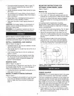
Страница 3: ... be moved to job site but should be mounted to stable level bench or table See Recommended Accessories page 17 3 MOUNTING INSTRUCTIONS FOR OPTIONAL STAND MODEL 22250 Refer to Figure 1 Material List Y2 x 15 x 22 particle board not supplied Four 14 20 x 11 1 1 Bolts with washers and nuts not supplied for mounting board to Multi Purpose Stand Four 8 1 25 x 30mm bolts with washers supplied with planer...

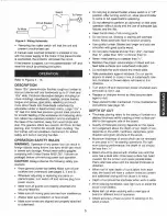
Страница 4: ...rong Receptacle with Adapter 4 A temporary 3 prong to 2 prong grounding adapter see Figure 3 is available for connecting plugs to a two pole outlet if it is properly grounded Do not use a 3 prong to 2 prong grounding adapter unless permitted by local and national codes and ordinances A 3 prong to 2 prong grounding adapter is not permitted in Canada Where a 3 prong to 2 prong grounding adapter is p...

Страница 5: ...ter turning switch on allow planer molder to come to full speed before operating Do not attempt to perform an abnormal or little used operation without study and the use of adequate jigs fixtures and the like Keep hands clear of all moving parts Do not force cut Slowing or stalling will overheat motor Allow automatic feed to function properly Use quality lumber Blades last longer and cuts are smoo...

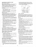
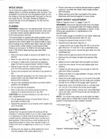
Страница 6: ...T Refer to Figures 5 and 15 pages 6 and 16 The planer molder has a 2 speed gearbox that feeds the workpiece at 13 feet per minute FPM for improved surface finish when molding or planing and 26 FPM for faster planing Be sure to unplug the planer molder from power source and turn planer molder OFF before adjusting the feed rate 6 Remove the socket head bolt Figure 15 Key No 33 that secures the gearb...

Страница 7: ...to a depression at either end of board caused by an uneven force on cutterhead when work is entering or leaving planer Snipe will occur when boards are not supported properly or when only one feed roller is in contact with work at beginning or end of cut To avoid snipe Gently push the board up while feeding the work until the outfeed roller starts advancing it 7 Move to the rear and receive planed...

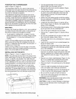
Страница 8: ...ise cuts and improved surface finish 9 Figure 7 Installing Cutter Bits and Knife Setting Gauge 8 Turn the planer molder off and unplug the planer molder from the power source Remove the knife cover and chip deflector Figure 15 Key Nos 4 and 6 Using the 6mm socket head bolt Figure 15 Key No 5 used to mount the knife cover mount the knife setting gauge to the top of the planer molder as shown in Fig...

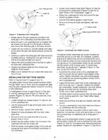
Страница 9: ...nation in the cutterhead 9 Loosen three washer head bolts Figure 15 Key No 3 and position chipbreaker Figure 15 Key No 2 see Position The Chipbreaker page 7 Rotate the cutterhead by hand and mount the two remaining pattern knives Use the knife setting gauge to align knives Be sure all knives and gibs are aligned tight and secure Y 1 Pattern Knife Figure 9 Cutterhead with Pattern Knives The planer ...

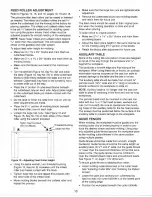
Страница 10: ...o their original posi tion when the molding operation is done and at all times when planing To raise rollers to original position Make two 213 s x 1W x 3W blocks and mark them as planing blocks Adjust the feed rollers height in the same manner as for the molding using 213 s portion of the blocks Retain the blocks after adjustment for future use AUXILIARY TABLE Some of the cutting bits and pattern ...

Страница 11: ...ll turn of the hand wheel Record the measurement this is the first pass measurement Switch on the planer molder and insert the work piece until the feed roller begins to advance the workpiece NOTE When using certain cutter bits knives the workpiece may feed in a jerky motion If this hap pens turn the handwheel and raise the table until the workpiece advances smoothly Revise the first pass measurem...

Страница 12: ...restarted LIFTING BARS Refer to Figure 16 page 18 Four lifting bars Key No 25 are provided to make relo cation of the planer molder easy Slide the four handles out of the infeed and outfeed ends of the table and use them to carry the planer molder to the desired location CAUTION The planer molder is top heavy and will tend to tip when moved Exercise caution whenever moving the planer molder 12 MAI...

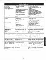
Страница 13: ...Dull knives 3 Replace knives per instructions see Knife Height Adjustment 1 Dull knives 1 Replace knives per instructions see Knife Height Adjustment 2 Too heavy a cut 2 Review Depth of Cut 3 Moisture content too high 3 Dry the wood or use dried wood Cutterhead not parallel with table Adjust elevation screws see Adjusting Depth of Cut Cutterhead not parallel with table Adjust elevation screws see ...

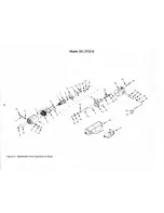
Страница 14: ...351 275210 I 21 14 17 1 l 30 40 43 4 8 _ 26 J y l 0 1 1 12 1 Ji __ 38 5 _ Lt 25 e 26 28 t 27 33 11 37 9 3 0 5 15 2 23 34 r 1 24 32 __ 1 I 26 22 13 11 1 9 12 Figure 14 Replacement Parts Illustration for Motor ...

Страница 15: ...66 00 Brush Holder 2 32 1766 00 5 0 8 x 8mm Pan Head Screw 1 11 3867 00 Carbon Brush Set of 2 1 33 8580 00 Motor Cord 1 12 3868 00 Brush Cap 2 34 1474 00 5mm Serrated Washer 1 13 1838 00 5 0 8 x 10mm Set Screw 2 35 1643 00 5 1 6 x 60mm Pan Head Screw 1 14 3869 00 Gearbox Bracket 1 36 2434 00 Strain Relief 1 01 15 3870 00 Gearbox 1 37 4288 00 5 1 6 x 70mm Pan Head Screw 2 16 3874 00 Pinion Shaft 1 ...

Страница 16: ...50 54 13 8 12 11 9 10 I Model 351 275210 8 8 I I I I Tyl Figure 15 Replacement Parts Illustration for Roller case 16 ...

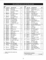
Страница 17: ...3 1 3 3 4 4 4 4 4 4 4 2 4 2 3 1 1 1 1 1 1 1 2 2 1 1 2 2 1 3 17 KEY NO PART NO DESCRIPTION QTY 35 8534 00 Gearbox Cover 1 36 1441 00 3BMI 34 Retaining Ring 3 37 8535 00 Spacer 35 38 STD315225 6202ZZ Bearing 2 39 8536 00 Cutterhead 1 40 8537 00 Planer Knife Set 1 41 8538 00 Cutterhead Gib 6 42 8560 00 8 1 25 x 16mm Set Screw 18 43 8539 00 Bit Gib 3 44 8540 00 Spacer 6 45 8541 00 Jack Screw 6 46 STD3...

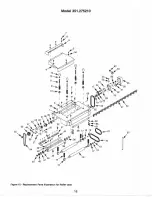
Страница 18: ...41 5 2 5 41 Model 351 275210 Figure 16 Replacement Parts Illustration for Base 18 ...

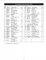
Страница 19: ...r 2 40 0179 00 6 1 0 x 20mm Socket 2 13 3873 00 4 x 4 x 8mm Key 2 Head Bolt 14 8561 00 Retaining Plate 2 41 STD851006 6mm Flat Washer 12 15 1505 00 6 1 0 x 12mm Socket 4 42 ST0851010 8mm Flat Washer 4 Head Bolt 43 8579 00 Shaft 1 16 STD852016 6mm Lock Washer 20 44 3886 00 Aligning Pin 2 17 8562 00 Right Guide Plate 1 45 8533 00 Line Cord 1 18 8563 00 Elevation Screw 1 46 3984 00 Strain Relief 1 19...

Страница 20: ...wing numbers Regina 566 5124 Montreal 333 5740 Toronto 744 4900 Halifax 454 2444 Kitchener 894 7590 Ottawa 738 4440 Vancouver 420 8211 When ordering repair parts always give 1 The Part Number 2 The Part Description 3 The Model Number 4 The name of the item WE SERVICE WHAT WE SELL WE MAKE THIS PLEDGE BECAUSE OUR CONCERN FOR OUR CUSTOMERS DOES NOT END WITH THE SALE TO HONOR OUR PLEDGE WE HAVE DEVELO...

Отзывы: