background image

45

MONTAJE

Figura 8

Ajuste del montaje del canal

Es posible ajustar la distancia a la cual se arroja la nieve cambiando el 
ángulo del montaje del canal. Para hacerlo:

Detenga el motor quitando la llave de encendido y afloje la perilla 
a mariposa de plástico que se encuentra en el lado izquierdo del 
montaje del canal.
Gire el canal hacia arriba o hacia abajo antes de apretar la perilla 
a mariposa. Vea la figura 8.

Prueba de control de la barrena

Compruebe el ajuste del control de la barrena de la siguiente forma:

Cuando se suelta el control de la barrena y está en posición 
desengranada arriba, el cable debe tener muy poco juego. NO 
debe estar tenso.
En un área bien ventilada, arranque el motor de la máquina 
quitanieve según se indica anteriormente en esta misma sección. 
Asegúrese de que del estrangulador está ajustado en posición 
FAST 

.

Parado en la posición del operador (detrás de la máquina 
quitanieve), engrane la barrena.
Deje la barrena engranada durante aproximadamente diez (10) 
segundos antes de soltar el control de la barrena. Repita esta 
operación varias veces.

 Con el control del estrangulador en posición rápida 

(dibujo 

de un conejo), y la barrena en posición desengranada arriba, 
camine al frente de la máquina. 
Confirme que la barrena ha dejado de girar por completo y no 
muestra NINGÚN signo de movimiento. Si la barrena muestra 
CUALQUIER signo de rotación, vuelva a la posición del operador 
y apague el motor inmediatamente. Espere a que TODAS las 
partes móviles se detengan antes de volver a ajustar el control de 
la barrena.
Para volver a ajustar el cable de control, afloje la tuerca hexago-
nal superior en la ménsula del cable de la barrena.
Ubique la ménsula hacia arriba para brindar más juego (o hacia 
abajo para aumentar la tensión del cable). Vea la figura 9.
 Vuelva a apretar la tuerca hexagonal superior.
Repita la 

prueba de control de la barrena

 para verificar 

que se ha logrado el ajuste adecuado.

1.

2.

1.

2.

3.

4.

5.

6.

7.

8.

9.
10.

Figura 9

WARNING

Antes de operar su máquina quitanieve, lea atentamente y cumpla 
todas las instrucciones que aparecen a continuación. Realice 
todos los ajustes para verificar que la máquina está operando con 
seguridad y correctamente.

Содержание 247.88355

Страница 1: ...ite www craftsman com CAUTION Before using this product read this manual and follow all safety rules and operating instructions Operator s Manual 24 SNOW THROWER Model No 247 883550 SAFETY ASSEMBLY OPERATION MAINTENANCE PARTS LIST ESPAÑOL 7 19 2007 FORM NO 769 01888D ...

Страница 2: ...e plate and spark plugs Repairs necessary because of operator negligence including but not limited to electrical and mechanical damage caused by improper storage bent crankshafts failure to use the proper grade and amount of engine oil or failure to maintain the equipment according to the instructions contained in the operator s manual Engine fuel system cleaning or repairs caused by fuel determin...

Страница 3: ...pport from a Sears technician on products requiring in home repair plus convenient repair scheduling Purchase a Repair Protection Agreement now and protect yourself from unexpected hassle and expense Once you purchase the Agreement a simple phone call is all that it takes for you to schedule service You can call anytime day or night or schedule a service appointment online Sears has over 12 000 pr...

Страница 4: ...st to outdoor temperature before starting to clear snow Safe Handling of Gasoline To avoid personal injury or property damage use extreme care in handling gasoline Gasoline is extremely flammable and the vapors are explosive Serious personal injury can occur when gasoline is spilled on yourself or your clothes which can ignite Wash your skin and change clothes immediately Use only an approved gasol...

Страница 5: ...til all moving parts have stopped before unclogging Use only attachments and accessories approved by the manufacturer e g wheel weights tire chains cabs etc If situations occur which are not covered in this manual use care and good judgment Contact your Sears Service Center for assistance MAINTENANCE STORAGE Never tamper with safety devices Check their proper operation regularly Refer to the maint...

Страница 6: ...This page left intentionally blank 6 ...

Страница 7: ...G MACHINE TO AVOID THROWN OBJECTS INJURIES NEVER DIRECT DISCHARGE AT BYSTANDERS USE EXTRA CAUTION WHEN OPERATING ON GRAVEL SURFACES READ OPERATOR S MANUAL 1 2 3 4 5 DANGER CLEAN OUT TOOL DANGER AVOID INJURY FROM ROTATING AUGER KEEP HANDS FEET AND CLOTHING AWAY DANGER NEVER PUT HAND IN CHUTE CONTACT WITH ROTATING PARTS CAN AMPUTATE FINGERS AND HANDS SHUT OFF ENGINE AND WAIT UNTIL AL L MOVING PARTS ...

Страница 8: ...TS Two replacement auger shear pins are included with this manual Refer to Replacing Shear Pins in the Operation section for more information regarding shear pin replacement ASSEMBLY Observe the lower rear area of the snow thrower to be sure both cables are aligned with roller guides before pivoting the handle upward See Figure 1 NOTE Make certain the upper ends of each cable are seated properly i...

Страница 9: ... into place use the palm of your hand to apply swift firm pressure to the back of each 5 a Remove the flat washer and hairpin clip from the end of the chute directional control b Insert the end of the chute directional control into the lower bracket and secure with the flat washer and hairpin clip just removed See Figure 5 If necessary the lower bracket can be adjusted Refer to Chute Bracket Adjus...

Страница 10: ...n the auger housing Use a middle or lower position when the area to be cleared is uneven such as a gravel driveway NOTE If you choose to operate the snow thrower on a gravel surface keep the skid shoes in position for maximum clearance between the ground and the shave plate To adjust the skid shoes Loosen the four hex nuts two on each side and carriage bolts Move skid shoes to desired position See...

Страница 11: ...ged for approximately ten 10 seconds before releasing the auger control Repeat this several times With the throttle control in the FAST rabbit position and the auger control in the disengaged up position walk to the front of the machine Confirm that the auger has completely stopped rotating and shows NO signs of motion If the auger shows ANY signs of rotating immediately return to the operator s p...

Страница 12: ...or the engine to start Remove the ignition key when the snow thrower is not in use NOTE Do not turn the ignition key in an attempt to start the engine Doing so may cause it to break CHOKE CONTROL The choke control is found on the rear of the engine and is activated by rotating the knob clockwise Activating the choke control closes the choke plate on the carburetor and aids in starting the engine F...

Страница 13: ...ad the gas cap to add gasoline to the fuel tank AUGER CONTROL The auger control is located on the left handle Squeeze the control grip against the handle to engage the augers and start snow throwing action Release to stop DRIVE CONTROL AUGER CONTROL LOCK The drive control is located on the right handle Squeeze the control grip against the handle to engage the wheel drive Release to stop NOTE Alway...

Страница 14: ... to spark plug Make certain the metal loop on the end of the spark plug wire inside the rubber boot is fastened securely over the metal tip on the spark plug Make certain both the auger control and drive control are in the disengaged released position Move throttle control up to FAST position Insert ignition key into slot Make sure it snaps into place Do not attempt to turn the key NOTE The engine...

Страница 15: ...engine Move throttle control to STOP STOP position Remove the ignition key and store in a safe place Wipe all snow and moisture from the area around the engine as well as the area in and around the drive control and auger control Also engage and release both controls several times TO ENGAGE DRIVE With the throttle control in the Fast position move shift lever into one of the five forward F positio...

Страница 16: ...e the oil drain plug See Figure 13 Be sure the gas cap is on and is tightened securely Clean area around oil drain plug Place approved recyclable oil container under oil drain plug Remove oil drain plug and drain oil NOTE Used oil must be disposed of at a proper collection center 6 Install oil drain plug and tighten securely 7 Refill the engine with recommended oil See Recommended Oil Usage chart ...

Страница 17: ...rests on the auger housing Remove the lower frame cover from the underside of the snow thrower by removing the four self tapping screws which secure it Apply a light coating of engine oil or 3 in 1 oil to the hex shaft See Figure 15 NOTE When lubricating the hex shaft be careful not to get any oil on the aluminum drive plate or rubber friction wheel Doing so will hinder the snow thrower s drive sy...

Страница 18: ...should NOT be tight Also if there is excessive slack in the drive cable or if the unit experiences intermittent drive while using the cable may need to be adjusted Check the adjustment of the drive control as follows With the drive control released push the snow thrower gently forward The unit should roll freely Engage the drive control and gently attempt to push the snow thrower forward The wheel...

Страница 19: ...r control cable Skid Shoes Refer to the Assembly section for instructions on adjusting the skid shoes BELT REPLACEMENT Auger Belt To remove and replace your snow thrower s auger belt proceed as follows To prevent spillage place a piece of plastic wrap under the gas cap and tighten securely Remove the plastic belt cover on the front of the engine by remov ing the two self tapping screws See Figure ...

Страница 20: ...the support bracket and the auger pulley See Figure 24 8 Reassemble auger belt by following instructions in reverse order NOTE Do NOT forget to reinstall the shoulder screw and reconnect the spring to the frame after installing a replacement auger belt Drive Belt To remove and replace your snow thrower s drive belt proceed as follows To prevent spillage place a piece of plastic wrap under the gas ...

Страница 21: ...embly of the belt FRICTION WHEEL REMOVAL If the snow thrower fails to drive with the drive control engaged and performing the drive control cable adjustment fails to correct the problem the friction wheel may need to be replaced Follow the instructions below Examine the friction wheel for signs of wear or cracking and replace if necessary To prevent spillage place a piece of plastic wrap under the...

Страница 22: ...nts If you re disassembling the friction wheel and replacing only the rubber ring proceed as follows Remove the four screws which secure the friction wheel s side plates together See Figure 30 Remove the rubber ring from between the plates Reassemble the side plates with a new rubber ring NOTE When reassembling the friction wheel assembly make sure that the rubber ring is centered and seated prope...

Страница 23: ...gas in the tank 1 Under heavy load or in high temperatures WARNING Before performing any type of maintenance service disengage all controls and stop the engine Wait until all moving parts have come to a complete stop Disconnect spark plug wire and ground it against the engine to prevent unintended starting Always wear safety glasses during operation or while performing any adjustments or repairs F...

Страница 24: ...Term Storage To avoid engine problems the fuel system should be emptied before storage for 30 days or longer WARNING Fuel left in engine during warm weather deteriorates and will cause serious starting problems 1 Run the engine until the fuel tank is empty and it stops due to lack of fuel Do not attempt to pour fuel from the engine WARNING Never use engine or carburetor cleaning products in the fu...

Страница 25: ...and snow from gas cap Be certain vent hole is clear 1 2 Unit fails to propel itself Drive cable in need of adjustment Drive belt loose or damaged 1 2 Adjust drive control cable Refer to Service and Maintenance section Replace drive belt Refer to Service and Mainte nance section 1 2 Unit fails to discharge snow Chute assembly clogged Foreign object lodged in auger Auger cable in need of adjustment ...

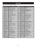
Страница 26: ...Craftsman Snow Thrower Model 247 883550 9 19 4 36 7 50 39 53 46 30 41 44 47 40 49 15 20 45 3 26 24 9 28 5 8 12 23 7 14 17 1 18 52 48 54 51 38 43 31 33 35 2 7 9 4 4 34 33 31 21 33 29 16 25 13 5 33 10 32 22 42 37 6 11 ...

Страница 27: ...75 ID x 1 85 OD 24 756 0981B Flat Pulley Idler 2 75 OD 25 790 00075 Housing Bearing 1 85 ID 26 790 00080A Bracket Auger Idler w Brake 27 618 04171A Gearbox Assembly Auger 24 Ref No Part No Description 28 684 04265 Housing Assembly Auger 24 29 684 04107 Spiral Assembly LH 30 684 04108 Spiral Assembly RH 31 731 04870 Spacer 1 25 OD x 75 ID x 1 00 32 736 0188 Washer Flat 76 x 1 49 x 06 33 741 0493A B...

Страница 28: ...28 PARTS LIST Craftsman Snow Thrower Model 247 883550 35 40 41 16 8 12 2 14 10 18 10 1 10 4 3 21 7 32 33 30 27 22 31 29 9 38 9 37 36 39 34 25 26 24 20 23 28 6 19 17 25 11 13 5 15 9 42 ...

Страница 29: ...l Speed Select 5 FW 2 RV 20 684 04104 Crank Assembly Chute 21 710 0449 Screw Carriage 5 16 18 2 25 Ref No Part No Description 22 710 04484 Screw 5 16 18 2 25 Gr5 23 714 0104 Pin Cotter 072 x 1 13 24 720 0201A Crank Knob 1 0 Dia x 3 2 Black 25 720 0284 Knob Assembly Black 5 16 18 26 726 0100 Cap Push 3 8 Rod 27 735 0234 Grommet 44 ID x 94 OD x 50 28 736 0185 Washer Flat 375 x 738 x 063 29 736 0159 ...

Страница 30: ...odel 247 883550 53 22 21 50 62 42 63 40 33 30 24 36 18 5 25 37 19 6 31 7 30 24 26 13 23 47 44 23 43 2 7 5 34 24 30 51 58 52 61 35 27 7 14 55 48 46 7 59 59 49 41 2 1 11 4 A B B A 8 26 16 28 45 29 17 3 9 54 32 60 57 56 60 20 10 15 12 38 39 64 ...

Страница 31: ...0096 Front Guide Bracket Auger Cable 32 790 00180A Frame 33 790 00206A Guide Bracket Auger Cable Ref No Part No Description 34 790 00207A Guide Bracket Drive Cable 35 790 00316 Cover Frame 36 634 04167A LH Wheel Assembly 13 x 4 x 6 634 04168A RH Wheel Assembly 13 x 4 x 6 37 731 04873 Spacer 1 25 x 75 x 3 0 38 738 04168 Axle 75 x 22 39 735 04100 Plug 1 2 ID 40 710 0809 Hex Screw 1 4 20 1 25 Gr5 41 ...

Страница 32: ...32 PARTS LIST Craftsman Engine Model LH195SP 67514 For Snow Thrower Model 247 883550 ...

Страница 33: ...r Assembly Incl 83 30588A Governor Spool 86 650488 Screw 1 4 20 x 1 1 4 Ref No Part No Description 89 610961 Flywheel Key 90 611195 Flywheel 92 650815 Belleville Washer 93 650816 Flywheel Nut 100 34443C Solid State Ignition 101 610118 Spark Plug Cover 102 651024 Solid State Mounting Stud 103 651007 Screw T 15 10 24 x 15 16 110 35182 Ground Wire 110A 36874 Ground Wire 119 36443 Cylinder Head Gasket...

Страница 34: ...le 350 570682A Primer Assembly 351 32180C Primer Line 355 590574 Starter Handle Mitten Grip 364 33333 Carburetor Cover Bracket 364A 37673 Locking Plate 365 650735 Screw 10 24 x 3 8 370A 36261 Instruction Decal 370B 35282 Speed Control Decal 370C 36501 Primer Decal 370D 36534 Caution Decal 370I 37119 Warning Decal 370K 36695 Starter Decal 380 640084B Carburetor Incl 184 390 590742 Rewind Starter 39...

Страница 35: ...30 631021A Inlet Needle Seat Clip Incl 31 31 631022 Spring Clip 32 27136A Bowl Drain Assembly 33 27554 Drain Plunger Gasket 36 632745 Main Nozzle Tube 37 632547 O Ring Main Nozzle Tube 40 640131 High Speed Bowl Nut 44 27110A Bowl Nut Washer 47 630748 Welch Plug Idle Mixture Well 48 631027 Welch Plug Atmospheric Vent 60 632760B Repair kit Incl Items Marked in Notes Ref No Part No Description 0 5907...

Страница 36: ...nty Defects are judged on normal engine performance The warranty is not related to an in use emission test Sears Emission Control Defects Warranty Provisions The following are specific provisions relative to your Emission Control Defects Warranty Coverage It is in addition to the Sears engine warranty for non regulated engines found in the Operating and Maintenance Instructions 1 Warranted Parts Co...

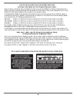
Страница 37: ...xample a typical walk behind lawn mower is used 20 to 25 hours per year Therefore the Emissions Durability Period of an engine with an intermediate rating would equate to 10 to 12 years The Air Index is a calculated number describing the relative level of emissions for a specific engine family The lower the Air Index the cleaner the engine This information is displayed in graphical form on the emi...

Страница 38: ... Reparaciones necesarias debido a negligencia del operador incluyendo entre otros daños mecánico y eléctrico ocasionado por un almace namiento no apropiado abolladura cigüeñal falla por el uso de aceite de grado y o cantidad no apropiada o falla por no dar mantenimiento al equipo de acuerdo con las instrucciones contenidas en el manual del operador Limpieza o reparaciones al motor sistema de combu...

Страница 39: ...ivo Ayuda rápida por teléfono asistencia telefónica a cargo de un técnico de Sears para los productos que requieren reparación a domicilio además de una programación conveniente para la reparación Una vez adquirido el Acuerdo puede programar el servicio con tan sólo realizar una llamada telefónica Puede llamar en cualquier momento del día o de la noche o programar un servicio en línea Sears dispon...

Страница 40: ... la temperatura exterior antes de comenzar a sacar la nieve Paraevitarlesionespersonalesodañosmaterialesseasumamentecuidadosoal manipularlagasolina Lagasolinaesaltamenteinflamableysusvaporespuedencausar explosiones Sepuedelesionargravementesiderramagasolinasobreustedosobrela ropayaquesepuedeprenderfuego Láveselapielycámbiesederopadeinmediato Utilice sólo recipientes para gasolina autorizados Apagu...

Страница 41: ...escarga No destape el montaje del canal mientras el motor está en funcionamiento Antes de destaparlo apague el motor y permanezca detrás de las manijas hasta que todas las partes móviles se hayan detenido Use sólo uniones y accesorios aprobados por el fabricante por ejemplo pesas para las ruedas cadenas para los neumáticos cabinas etc Si se presentan situaciones que no están previstas en este manu...

Страница 42: ... de cuchilla de barrena de repuesto Consulte la sección Barrenas en la sección de Servicio y Mantenimiento para obtener más información sobre el reemplazo de los pasadores de cuchilla de barrena MONTAJE Observe el área inferior trasera de la máquina quitanieve para asegurarse de que ambos cables estén alineados con las guías rotatorias antes de girar la manija hacia arriba Vea la figura 1 NOTA Ase...

Страница 43: ... la palma de su mano para aplicar una presión rápida y firme en la parte posterior de cada uno 5 a Quite la arandela plana y el broche de horquilla del extremo del control direccional del canal b Inserte el extremo del control direccional del canal en el soporte inferior y asegúrelo mediante la arandela plana y el broche de horquilla que acaba de retirar Vea la figura 5 Si es necesario puede ajust...

Страница 44: ...ja de la barrena Use las posiciones media o baja cuando la superficie que desee limpiar sea despareja como un camino de grava NOTA Si tiene que usar la máquina quitanieve sobre grava mantenga la zapata antideslizante en la posición más elevada para lograr una separación máxima entre el piso y la placa de raspado Para ajustar las zapatas antideslizantes Afloje las cuatros tuercas hexagonales dos en...

Страница 45: ... segundos antes de soltar el control de la barrena Repita esta operación varias veces Con el control del estrangulador en posición rápida dibujo de un conejo y la barrena en posición desengranada arriba camine al frente de la máquina Confirme que la barrena ha dejado de girar por completo y no muestra NINGÚN signo de movimiento Si la barrena muestra CUALQUIER signo de rotación vuelva a la posición...

Страница 46: ...nieve NOTE No gire la llave de encendido para intentar arrancar el motor Al hacerlo podría romperla CONTROL DE OBTURACIÓN El control de obturación se encuentra en la parte posterior del motor y se activa haciendo girar la perilla en sentido de las agujas del reloj Al activar el control de obturación se cierra la placa de obturación del carburador y se ayuda a encender el motor Figura 10 Cumple con...

Страница 47: ...través del llenado de aceite TAPÓN DE COMBUSTIBLE Desenrosque el tapón de combustible para agregar gasolina al tanque de combustible ZAPATAS ANTIDESLIZANTES Ubique las zapatas antideslizantes en función de las condiciones de la superficie Ajuste hacia arriba si la nieve está muy compactada Ajústelas hacia abajo si usa la máquina en gravas o superficies con piedras trituradas CONTROL DE LA BARRENA ...

Страница 48: ...ar derramamientos Llene el tanque de combustible con gasolina sin plomo limpia y fresca Nunca llene completamente el tanque Llene el tanque hasta 1 2 pulg por debajodeltope dejandoasíespacioparaladilatacióndelcombustible Asegúrese de limpiar el combustible que se haya derramado antes de arrancar el motor ENCENDIDO DEL MOTOR Conecte el cable de la bujía a la misma Compruebe que el lazo de metal del...

Страница 49: ...ermita que se desenganche Mantenga la manija del arrancador firmemente sujeta y permita que la cuerda retroceda lentamente 5 Mientras se calienta el motor gire lentamente el control del obturador a posición OFF apagado Si el motor falla vuelva a girar rápidamente el obturador a posición FULL y luego lentamente a posición OFF de nuevo 1 NOTA permita que el motor se caliente durante unos minutos tra...

Страница 50: ...o caliente por su uso reciente Localice el tapón de drenaje del aceite Vea la figura 12 Asegúrese de que la tapa de la gasolina está puesta y bien ajustada Limpie el área alrededor del tapón de drenaje del aceite Coloque un recipiente de aceite reciclable aprobado bajo el tapón del drenaje del aceite Saque el tapón de drenaje del aceite y drene el aceite NOTA el aceite usado debe desecharse en un ...

Страница 51: ... tras cada 25 horas de operación Gire con cuidado la máquina quitanieve hacia arriba y hacia delante de manera que quede apoyada sobre la caja de la barrena Retire la cubierta del marco inferior quitando los cuatro tornillos que la aseguran Aplique al eje hexagonal una capa ligera de una grasa multiusos apta para condiciones climáticas múltiples Vea la figura 14 NOTA Evite los derrames de aceite s...

Страница 52: ...ansmisión Cuando se suelta el control de la transmisión y está en posición desenganchada arriba el cable debe tener muy poco juego NO debe estar tenso También si hay excesivo flojo en el cable de paseo o si la unidad experimenta el paseo intermitente usando el cable puede tener que ser ajustado Compruebe el ajuste del control de la transmisión de la siguiente forma Cuando suelte el control de la t...

Страница 53: ...aje para ajustar Las zapatas antidesli zantes REEMPLAZO DE LA CORREA La Correa de la barrena Para retirar y reemplazar la correa de la barrena de su máquina quitanieve proceda como se indica a continuación Drene la gasolina de la máquina quitanieve o coloque un trozo de plástico debajo del tapón de llenado del combustible Saque la cubierta plástica de la correa ubicada en el frente del motor Para ...

Страница 54: ... Vea la figura 23 8 Para realizar el reensamblado de la correa de la barrena siga las instrucciones en orden inverso NOTA NO olvide volver a instalar el tornillo con reborde y volver a conectar el resorte al marco tras instalar una correa de la barrena de repuesto La correa de la transmisión Para retirar y reemplazar la correa de la barrena de su máquina quitanieve proceda como se indica a continu...

Страница 55: ...ACCIÓN DE LA RUEDA DE FRICCIÓN Si la máquina quitanieve no se acciona cuando el control de la trans misión está engranado y si al realizar el ajuste del cable de control de la transmisión que aparece el problema no se corrige tal vez se deba reemplazar la rueda de fricción Siga las instrucciones que aparecen a continuación Examine la rueda de fricción en busca de signos de desgaste o grietas y ree...

Страница 56: ...la rueda de fricción para reemplazar únicamente el anillo de goma proceda como se indica a continuación Saque los cuatro tornillos de mantienen unidas las placas laterales de la rueda de fricción Vea la figura 29 Retire el anillo de goma de entre las placas Reensamble las placas laterales con un nuevo anillo de goma NOTA Al reensamblar el conjunto de la rueda de fricción asegúrese de que el anillo...

Страница 57: ...e control y pivotes 1 2 3 Cambio Limpio o sustituyen Lubricación con petróleo ligero 1 2 3 50 horas El aceite de motor 1 Cambio 1 Anualmente o 100 horas Bujía 1 Limpio sustituya nuevo hueco 1 Antes de Almacenaje Sistema de combustible 1 El motor dirigido hasta que esto se pare a falta del combustible o añada un aditivo de gasolina al gas en el tanque 1 Bajo carga pesada o en temperaturas altas Sig...

Страница 58: ...a máquina quitanieve en un galpón de depósito metálico o con poca ventilación tenga especial cuidado de realizarle un tratamiento anti oxidante al equipo Use aceite ligero o silicón para recubrir el equipo especialmente las cadenas los resortes los cojinetes y los cables Elimine todo el polvo del exterior del motor y del equipo Siga las recomendaciones de lubricación en la sección de mantenimiento...

Страница 59: ...ibración Hay piezas que están flojas o la barrena está dañada 1 Detenga el motor de inmediato y desconecte el cable de la bujía Ajuste todos los pernos y las tuercas Si la vibración continúa lleve la unidad a reparar a un centro de partes y reparación Sears 1 Pérdida de potencia El cable de la bujía está flojo El orificio de ventilación del tapón de llenado del combustible está obstruido 1 2 Conec...

Страница 60: ... de acuerdo con el funcionamiento normal de un motor La garantía no está relacionada con una prueba de emisiones en uso Disposiciones de la garantía Sears para defectos en el control de emisiones Las siguientes son disposiciones específicas relacionadas con la cobertura de la garantía para defectos en el control de emisiones Es un añadido a la garantía de motor Sears para motores no regulados que s...

Страница 61: ...ño Por lo tanto el Período de Duración de Emisiones de un motor con una clasificación intermedia sería equivalente a entre 10 y 12 años Laclasificación de aire es un número calculado para describir el nivel relativo de emisiones para un grupo de motores en particular Cuanto menor sea la clasificación de aire mayor es la limpieza del motor La información se presenta de forma gráfica en la etiqueta ...

Страница 62: ...NOTAS 62 ...

Страница 63: ...NOTAS 63 ...

Страница 64: ...iances and items like garage door openers and water heaters 1 800 4 MY HOME 1 800 469 4663 Call anytime day or night U S A and Canada www sears com www sears ca For expert home solutions advice www managemyhome com Our Home For repair of carry in items like vacuums lawn equipment and electronics call or go on line for the location of your nearest Sears Parts Repair Service Center 1 800 488 1222 U ...

Отзывы: