background image

Содержание 139.53930DM

Страница 1: ...Fasten the manual near the garage door after installation Periodic checks of the opener are required to ensure safe operation c us Leer y seguir todas las reglas de seguridad y las instrucciones de operacion antes de usar este producto por primera vez Guardar este manual cerca de la puerta de la cochera Se deben realizar revisiones periodicas del abridor de puertas para asegurar su operacion segur...

Страница 2: ...en the door manually 31 Care of your garage door opener 32 Having a problem 33 Diagnostic chart 34 Programming 35 36 To add or reprogram a hand held remote control 35 To erase all codes 35 3 Function Remotes 35 To add reprogram or change a Keyless Entry PIN 36 Repair Parts 37 38 Rail assembly parts 37 Installation parts 37 Motor unit assembly parts 38 Accessories 39 Warranty 39 Repair Parts and Se...

Страница 3: ...ced garagedoor may NOTreversewhen required NEVERtry to loosen move or adjust garagedoor door springs cables pulleys brackets or their hardware all of which are under EXTREMEtension DisableALL locks and removeALL ropes connected to garagedoor BEFORE installing and operating garagedoor opener to avoid entanglement To prevent damageto garage door and opener ALWAYSdisable locks BEFORE installing and o...

Страница 4: ...door must not exceed 1 4 6 mm Otherwise the safety reversal system may not work properly See Adjustment Step 3 Floor or door should be repaired SECTIONAL DOOR INSTALLATIONS Do you have a steel aluminum fiberglass or glass panel door If so horizontal and vertical reinforcement is required Installation Step 11 The opener should be installed above the center of the door If there is a torsion spring o...

Страница 5: ...edto eliminate the gap ONE PIECE DOOR WITHOUT TRACK FINISHED CEILING Support bracket fastening hardware is required See page 16 Safety Reversing Sensor Header Wail Rail Slack in chain tension is normal when garage door is closed I Access Door O Gap between floor Safety Reversing Sensor Wall mounted Door Control and bottom of door must not exceed 1 4 6 mm Motor Unit leader Vail CLOSED POSITION Rail...

Страница 6: ...ent is complete Standard Control Console Motor Unit with a Light Lens SECURITY 3 Function Remote Control with visor clip 2 Trolley Rail Center Back Sections Chain Spreader _1 _ Ol _1 _ Hanging Brackets Idler Pulley Rail Fron header _ _ i Header Bracket Chain and Cable Door Bracket Curved Door Arm Section U Bracket Safety Sensor Bracket 2 The Protector System 2 Safety Reversing Sensors 1 Sending Ey...

Страница 7: ...haft 1 Spacer 2 1 Master Link 2 Idler Bolt 1 Carriage Bolt Wing Nut 1 4 20xl 2 2 1 4 20 2 INSTALLATION HARDWARE Ring Nut 5 16 18 6 Fastener 3 Handle Lag Screw 5 16 9xl 5 8 2 111111111111_ Lag Screw 5 16 18xl 7 8 2 _ng Screw 1 4 14x5 8 2 _ lllllllllID Hex Bolt 5 16 18x7 8 4 Lock Washer 5 16 5 Screw 6ABx1 1 4 2 Drywall Anchors 2 Insulated Staples Not shown Screw 6 32x1 2 ol Clevis Pin Clevis Pin Cle...

Страница 8: ...s into the larger ones Tabs along the side will lock into place To prevent INJURYfrom pinching keep hands and fingers away from the joints while assembling the rail 3 Place the motor unit on packing material to protect the cover and rest the back end of the rail on top For convenience put a support under the front end of the rail 4 As a temporary stop insert a screwdriver into the hole 10 25 cm fr...

Страница 9: ... Bolt 1 4 20x2 1 2 Washer 5 8 _ Spacer Cover Protection Bolt Hole Chain Bolt Spreader U Bracket Spacer Washer 5 8 _l Lock Nut _ 1 4 20 ASSEMBLY STEP 3 Install the Idler PuUey 1 Lay the chain cable beside the rail as shown Grasp the end of the cable and pass approximately 12 30 cm of cable through the window Allow it to hang until Assembly Step 4 2 Remove the tape from the idler pulley The inside c...

Страница 10: ...h must engage the chain Figure 2 4 Check to make sure the chain is not twisted then connect it to the threaded shaft with the remaining master link 5 Thread the inner nut and lock washer onto the trolley threaded shaft Figure 3 6 Insert the trolley threaded shaft through the hole in the trolley Be sure the chain is not twisted Figure 3 7 Loosely thread the outer nut onto the trolley threaded shaft...

Страница 11: ...NS Toreduce theriskofSEVERE INJURY orDEATH 1 READAND FOLLOWALL INSTALLATION WARNINGSAND INSTRUCTIONS 2 Install garage door opener ONLYon properly balanced and lubricated garage door An improperly balanceddoor may NOTreversewhen required and could result in SEVERE INJURYor DEATH 3 ALL repairs to cables spring assembliesand other hardware MUST be made by a trained door systemstechnician BEFORE insta...

Страница 12: ...arance is minimal It may be mounted on the wall upside down if necessary to gain approximately 1 2 1 cm If you need to install the header bracket on a 2x4 on wall or ceiling use lag screws not provided to securely fasten the 2x4 to structural supports as shown here and on page 13 3 Open your door to the highest point of travel as shown Draw an intersecting horizontal line on the header wall above ...

Страница 13: ...ovided HARDWARE SHOWN ACTUAL SIZE 5 16 9xl 5 8 Wall Mount Optional Mounting Holes Header Wall 2x4 Structural Support J t Horizontal Line Highest Point of Garage Door Travel Vertical Centerline of Garage Door Lag Screws 5 16 9xl 5 8 pring Garage Door Vertical Centerline of Garage Door CEILING HEADER BRACKET INSTALLATION Extend the vertical centerline onto the ceiling as shown Center the bracket on ...

Страница 14: ... ll need help Have someone hold the opener securely on a temporary support to allow the rail to clear the spring Position the rail bracket against the header bracket Align the bracket holes and join with a clevis pin 5 16 x1 1 2 as shown Insert a ring fastener to secure I Header Wall Header Bracket Mounting Hole 0 i Door Temporary Support HARDWARE SHOWN ACTUAL SIZE Clevis Pin 5 16 xl 1 2 Ring Fast...

Страница 15: ...lley toward the motor unit The trolley can remain disconnected until Installation Step 12 is completed To prevent damageto garage door rest garage door opener rail on 2x4 placed on top section of door Rail Door from ceiling olley lease Arm t J ENGAGED RELEASED _L_ ONE PIECE DOOR WITHOUT TRACK A 2x4 on its side is convenient for setting an ideal door to rail distance Raise the opener onto a steplad...

Страница 16: ...bracket if the bracket is not centered above the door 7 Remove the 2x4 Operate the door manually If the door hits the rail raise the header bracket NOTE DO NOT connect power to opener at this time HARDWARE SHOWN ACTUAL SIZE _l Lla Ic elw ll _ll xll_718 I I I P D Hex B01t 5 16 18x7 8 Nut 5 16 18 Lock Washer 5 16 To avoid possible SERIOUSINJURYfrom afalling garage door opener fasten it SECURELY to s...

Страница 17: ... red white to red 5 Position the antenna wire as shown 6 Use tacks or staples to permanently attach entrapment warning label to wall near door control and manual release safety reverse test label in a prominent location on inside of garage door NOTE DO NOT connect power and operate opener at this time The trolley will travel to the full open position but will not return to the close position until...

Страница 18: ... 1 Insert one end of the emergency release rope through the handle Make sure that NOTICE is right side up Tie a knot at least 1 inch 2 5 cm from the end of the emergency release rope 2 Insert the other end of the emergency release rope through the hole in the trolley release arm Mount the emergency release within reach but at least 6 feet 1 83 m above the floor avoiding contact with vehicles to pr...

Страница 19: ...tion and wiring MUST be in compliance with all local electrical and building codes NEVERuse an extension cord 2 wire adapter or change plug in any way to makeit fit outlet Besure the opener is grounded PERMANENT WIRING CONNECTION If permanent wiring is required by your local code refer to the following procedure To make a permanent connection through the 7 8 hole in the top of the motor unit Remov...

Страница 20: ...e mounting brackets are designed to clip onto the track of sectional garage doors without additional hardware Be sure power is NOTconnected to the garagedoor opener BEFORE installing the safety reversing sensor To prevent SERIOUSINJURY or DEATHfrom a closing garagedoor Correctly connect and align the safety reversingsensor This required safety deviceMUST NOTbe disabled Install the safety reversing...

Страница 21: ...h brackets to wall with lag screws Not provided If using extension brackets or wood blocks adjust right and left assemblies to the same distance out from the mounting surface Make sure all door hardware obstructions are cleared Floor installation Figure 4 Use wood blocks or extension brackets See Accessories to elevate sensor brackets so the lenses will be no higher than 6 15 cm above the floor Ca...

Страница 22: ...ng directly at the receiving eye Lock in place Loosen the receiving eye wing nut and adjust sensor until it receives the sender s beam When the green indicator light glows steadily tighten the wing nut Figure 5 Carriage Bolt _ 1 4 20x 1 2 I _ _ Wing Nut 0 TROUBLESHOOTING THE SAFETY REVERSING SENSORS 1 If the sending eye indicator light does not glow steadily after installation check for Electric p...

Страница 23: ... light weight doors using a vertical angle iron brace between the door panel support and the door bracket Drill 3 16 fastening holes Secure the door bracket using the two 1 4 14x5 8 self threading screws Figure 2A Alternately use two 5 16 bolts lock washers and nuts not provided Figure 2B Metal insulated or light weight factory reinforced doors Drill 3 16 fastening holes Secure the door bracket us...

Страница 24: ...ing Screw 1 4 14x5 8 NOTE The door bracket may be installed on the top edge of the door if required for your installation Refer to the dotted line optional placement drawing Header Wall 2x4 Support Door Bracket Optional Placement of Door Bracket Vertical Centerline of Garage Door Finished Ceiling HORIZONTALAND VERTICAL REINFORCEMENTIS NEEDED FOR LIGHTWEIGHTGARAGE DOORS FIBERGLASS ALUMINUM STEEL DO...

Страница 25: ...door arm rigidity Figure 3 Hole alignment alternative If holes in curved arm are above holes in straight arm disconnect straight arm Cut about 6 15 cm from the solid end Reconnect to trolley with cut end down as shown Bring arm sections together Find two pairs of holes that line up and join with bolts lock washers and nuts Pull the emergency release handle toward the opener at a 45 angle so that t...

Страница 26: ...justment screw clockwise 4 complete turns Figure 6 Inner Trolley Emerg L ency Release Handle Closed I Door Inner Trolley Figure 5 CORRECT i Door Arm Groove INCORRECT Door Bracket Clevis Pin Straight 5 16 x1 1 4 Arm Bolts 5 16 18x7 8 Fastener Lock Washers 5 16 Nuts 5 16 18 Curved Door Arm Press the Door Control push button The trolley will travel to the fully closed position Manually close the door...

Страница 27: ...force as explained in Adjustment Step 2 If the door does not close completely Increase down travel Turn the down limit adjustment screw counterclockwise One turn equals 2 5 cm of travel If door still won t close completely and the trolley bumps into the pulley bracket page 4 try lengthening the door arm page 25 and decreasing the down limit If the opener reverses in fully closed position Decrease ...

Страница 28: ... floor HOW AND WHEN TO ADJUST THE FORCES 1 Test the DOWN close force Grasp the door bottom when the door is about halfway through DOWN close travel The door should reverse Reversal halfway through down travel does not guarantee reversal on a 1 1 2 3 8 cm obstruction See Adjustment Step 3 page 29 If the door is hard to hold or doesn t reverse DECREASE the DOWN close force by turning the control cou...

Страница 29: ...o or adjustment of the opener Without a properly installed safety reversalsystem persons particularly small children could be SERIOUSLYINJUREDor KILLEDby a closing garagedoor Safety reversalsystem MUST be tested every month If one control force or travel limits is adjusted the other control may also needadjustment After ANY adjustments are made the safety reversalsystem MUST betested Door MUST rev...

Страница 30: ...Garage Door Opener Your Security _ opener and hand held remote control have been factory set to a matching code which changes with each use randomly accessing over 100 billion new codes Your opener will operate with up to eight Security _ remote controls and one Security _ Keyless Entry System If you purchase a new remote or if you wish to deactivate any remote follow the instructions in the Progr...

Страница 31: ...open or closed If rope knot becomes untied you could fall DISCONNECT THE TROLLEY The door should be fully closed if possible Pull down on the emergency release handle so that the trolley release arm snaps into a vertical position and lift the door manually The lockout feature prevents the trolley from reconnecting automatically and the door can be raised and lowered manually as often as necessary ...

Страница 32: ...nal lubrication Do not grease the door tracks To prevent possible SERIOUSINJURYor DEATH NEVERallow small children near batteries If battery is swallowed immediately notify doctor To reduce risk of fire explosion or chemical burn ReplaceONLYwith 3V2032 coin batteries DONOTrecharge disassemble heat above 100 C 212 F or incinerate The lithium battery should produce power for up to 5 years To replace ...

Страница 33: ...e need for occasional adjustment for the force and limit settings is normal Weather conditions in particular can affect door travel Refer to Adjustment Step 1 Adjust the UP and DOWN Travel Limits Decrease down travel by turning down limit adjustment screw clockwise 5 My lights will not turn off when door is open The garage door opener is equipped with a security light feature This feature activate...

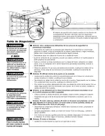
Страница 34: ...ng eye Align sensors if the indicator lights glow replace the wires for the sensors If the sensor indicator lights do not light replace the safety sensors Symptom LED is not lit on door control Inspect door control wires for a short staple in wire replace as needed Disconnect wires at door control touch wires together If motor unit activates replace door control If motor unit does not activate dis...

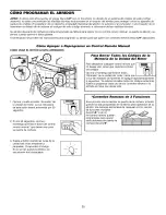
Страница 35: ...l USING THE LEARN BUTTON To Erase All Codes From Motor Unit Memory To deactivate any unwanted remote first erase all codes Press and hold the learn button on motor unit until the learn indicator light goes out approximately 6 seconds All previous codes are now erased Reprogram each entry you wish to use lote or keyless 1 Press and release the learn button on the motor unit The learn indicator ligh...

Страница 36: ...and will no longer open the door It can be used to close the door even after it has expired To set a temporary PIN 1 Press the four buttons for your personal entry PIN not the last temporary PIN then press and hold the 8 button The opener light will blink three times Release the button 2 Press the temporary 4 digit PIN you have chosen then press Enter The opener light will blink four times 3 To se...

Страница 37: ...047 178B35 178B34 12B776 41A5034 41A5266 1 41A5258 25 114A3613 Standard control console 3V 2032 Lithium battery 3 function remote control housing no circuit board Visor clip Emergency release rope and handle assembly Header bracket w clevis pin and fastener 2 Conductor bell wire white and white red Door bracket w clevis pin and fastener Curved door arm section Straight door arm section Hanging bra...

Страница 38: ...ase 17 Drive worm gear kit w grease roll pins 2 Line cord 18 End panel Light socket 19 Lens Capacitor 1 2 HP Capacitor bracket Terminal block w screws Universal replacement motor bracket assembly Complete with Motor worm bracket bearing assembly RPM sensor 41A5525 63 41A2818 41 D3452 41A2822 1 41 C4398A 41AC150 1M 41 C5497 41 C5498 41D179 41A2826 41A2825 Cover Limit switch drive retainer Limit swi...

Страница 39: ... 1 year from the date of purchase replacement parts for any defective parts on this product will be furnished free of charge You pay for labor ADDITIONAL LIMITED WARRANTY ON MOTOR From the 91st day and through 4 years if the motor on this product is defective a replacement motor will be furnished free of charge You pay for labor WARRANTY RESTRICTION This Craftsman Garage Door Opener Limited Warran...

Страница 40: ...30 C6mo usar la unidad de control de pared 31 C6mo abrir la puerta manualmente 31 Mantenimiento de su abridor de puerta de cochera 32 Si tiene algQn problema 33 Tabla de diagn6stico 34 C6mo Programar el Abridor 35 36 C6mo agregar o reprogramar un control remoto manual 35 C6mo borrar todos los c6digos 35 Controles remotos de 3 funciones 35 C6mo agregar reprogramar o cambiar un c6digo de entrada sin...

Страница 41: ...retroceda como se requiere NUNCAintente aflojar mover ni ajustar la puerta de su cochera los resortes de la puerta los cables las poleas las m_nsulas ni la tornilleria puestodos estos elementos est_ nbajo tensi6n EXTREMA Quite TODOSlos seguros y retire TODASlas cuerdas conectadasa la puerta decochera ANTES de instalar y operar el abridor de la puerta de cochera paraevitar que se enreden Paraevitar...

Страница 42: ...uncione correctamente Vea Ajustes Paso 3 Sera necesario reparar ya sea el piso o la puerta INSTALACl0N CON UNA PUERTA SECClONAL Si tiene una puerta de acero aluminio fibra de vidrio o con paneles de vidrio necesitara refuerzos verticales y horizontales en la puerta Instalaci6n Paso 11 El abridor se debe instalar por encima del centro de la puerta pero si existe alg5n resorte de tensi6n o placa de ...

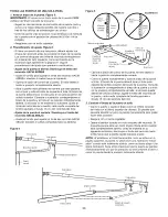
Страница 43: ...A DE UNA SOLA PIEZA SIN CARRIL Pareddelantera Sensor de seguridad de reversa Ele _ _acio entre la base la puerta y el piso nodebe de exceder6 mm 1 4de pulg CIELORASO CON ACABADO Serequiere mensuiade soporte y tornitloso sujetadores Veata p_tgina16 Riel La holgura en la tensi6n de la cadena es normal cuande la puerta se encuentracerrada J Puertade acceso Sensor de seguridad de reversa Unidaddel mot...

Страница 44: ...terminado Consola de ControlEstandar Unidaddel motorcon uno lente SECURITY Control remotode 3 Funciones con clip para el visor 2 Trole Desplegadorde Cadena Seccionescentral y posteriordel riel _Io flo flo Mensulaspara colgar Poleade la cadena Secci6ndelantera del riel cabezal Sensoresdel sistemade retroceso de seguridad 2 Cadenay cable Mensuladel cabezal Mensulade la puerta ProtectorSystem Dossens...

Страница 45: ... trole 1 TORNILLER A Y PIEZAS PARA LA INSTALACION Perno de coche de 1 4 20xl 2 pulg 2 Tuercade mariposa 1 4 20pulg 2 IIIIIIIIIII1 Tornillode cabezacuadrada de 5 16 18xl 7 8 pulg 2 Anillo sujetador 3 Tuercade 5 16 18pulg 6 Pernohexagonal de 5 16 18x7 8pulg 4 Arandelade 5 16pulg 5 lllllMIMl l lllllllllllll Tornillo6ABx1 1 4 pulg 2 de 1 4 14x5 8de pulg 2 Taquetepara murofalso 2 Tornillode 6 32xl pulg...

Страница 46: ...e los extremos mAs pequeSos dentro de los mAs grandes Las pestaSas que se encuentran a Io largo de los lados del riel se van a ajustar en su lugar Paraevitar QUESE PELLIZQUE conserve los manos y dedos lejos de las juntas cuando monte el reil 3 Coloque el motor sobre el material de empaque para proteger la cubierta del mismo y apoye el extremo posterior del riel encima Para que le resulte mAs c6mod...

Страница 47: ...3 4 pulg Perno Mensula en U Arandela5 8 pulg Separador _ Orificio para_ el perno protector de la cubierta Desplegador de cadena Se Arandela5 8 pulg_ _ Tuercade seguridad de 1 4 pulg 2O MONTAJE PASO 3 Instale la Polea Loca 1 Ponga la cadena y cable a un lado del riel como se muestra en la ilustraci6n Tome el extremo del cable y pase por la ventana aproximadamente 30 cm 12 pulg D6jelo que cuelgue ha...

Страница 48: ...role Los dientes de la rueda dentada deben enganchar la cadena Figura 2 4 Cerci6rese de que la cadena no est6 torcida luego con_ctela al eje roscado con el enlace maestro restante 5 Enrosque la tuerca interna y la arandela en el eje roscado del trole Figura 3 6 Pase el eje roscado del trole a trav_s del orificio que tiene el trole Cerci6rese de que la cadena no este torcida Figura 3 7 Enrosque la ...

Страница 49: ...puerta de cochera s61osi la puerta de la cochera est debidamente balanceaday lubricada Si la puerta no est debidamente balanceadaes posible que NO retroceda cuando se requiera Io que podria ocasionar una LESIONGRAVEo INOLUSOLA MUERTE 3 TODASlas reparacionesde los cables resortesy otras piezaslas DEBEIlevar a cabo un t_cnico especializadoen sistemas depuertas ANTESde instalar el abridor 4 Quite TOD...

Страница 50: ...ro de la puerta pero Qnicamente si un resorte de torsibn o un placa central de apoyo se encuentra en el recorrido Tambien cuando el espacio es reducido se puede instalar la mensula en el cielo raso o plafon de la cochera vea la pagina 13 Asimismo se puede instalar invertida sobre la pared si es necesario esto le darn aproximadamente 1 cm 1 2 de pulg de espacio Si necesita instalar la mensuta det c...

Страница 51: ... SU TAMAI IO REAL de 5 16 p0r 9xl 5 8 de pulgadas Punto masalto del recorridode lapuerta de la garaje Montajeen la pared 0 q Orificiosopcionales para la instalacidn Resorte de la puerta Puerta de la cochera Linea central de la puerta de garaje INSTALACION DE LA MI_NSULA DEL CABEZAL EN EL ClELO RASO Extienda la linea central vertical sobre et cieto raso como se muestra en la ilustracion Coloque la ...

Страница 52: ...soporte temporal para permitir que el riel pueda librar el resorte Coloque la m_nsula del riel contra la m_nsula del cabezal Coloque el extremo del riel delantero dentro de la m_nsula del cabezal y una ambos elementos con un pasador de chaveta de 5 16 por 1 1 2 de pulg como se muestra en la ilustraci6n Suj_telos con un anillo sujetador Mensuladel cabezal PoleaIoca Orificio de montaje Puerta de la ...

Страница 53: ...i6n Paraevitar que la puerta de cochera sufra da_os apoye el riel del abridor de la misma sobre un pedazode maderade 5x10 cm 2x4 pulg colocado en la secci6n superior de la puerta Riel Puerta El pedazode maderade 5x10 cm 2x4pulg se utiliza para determinar ladistancia correctade instalaci6ndesde el techo deiia oc id3 n CONECTADO PUERTA DE UNA SOLA PIEZA SIN CARRIL Coloque un pedazo de madera de 5x10...

Страница 54: ...x4 pulg Haga funcionar la puerta manuatmente Si la puerta gotpea et riet suba la mensuta del cabezal NOTA NO conecte el abridor a la fuente de energfa electrica en este momento ESTAS PIEZAS SE MUESTRAN EN SU TAMAI_IO REAL de 5 16 18xl 7 8 de pulg Perno hexagonal Tuercade de 5 16 18x7 8de pulg 5 16de pulg 18 Arandela de 5 16de pulg Paraevitar la posibilidad de una LESIONGRAVEsi se cae el abridor de...

Страница 55: ...ar permanentemente Ia catcomania de advertencia sobre et riesgo de quedar atrapado esta catcomania debe estar en Ia pared y cerca det control de Ia puerta La calcomania de advertencia de Ia prueba de retroceso de seguridad y Iiberacion manual debe cotocarse en un punto prominente det interior de Ia puerta de Ia cochera NOTA NO conecte el abridor a la energfa electrica ni Io haga funcionar en este ...

Страница 56: ...ija Verifique que la palabra NOTICE aviso este mirando hacia arriba Asegurela con un nudo por Io menosa 2 5 cm l del extremo de la cuerda de desenganche de emergencia 2 Inserte elotro extremo de la cuerda de desenganche de emergencia a trav_sdelorificio delbrazo de desenganche delcarro Instale elabridor de emergencia donde pueda ser alcanzado almenosa 6 pies 1 83 m sobre elnivelpiso donde no est_ ...

Страница 57: ... et cable de tres entradas Conecte el cable negro tinea al tornillo de la terminal de cobre el cable btanco neutral al tornillo de la terminal color plata y et cable verde tierra at tornillo verde de la puesta a tierra El abridor debe estar puesto a tierra Vuetva a poner la cubierta en su tugar y atornflleta Para evitar dificultades con la instalacibn no encienda ni use el abridor en este momento ...

Страница 58: ...la necesidad de tornilleria ni piezas adicionates Cerci6rese de que la energia el_ctrica NOest_ conectadaal abridor de la puerta de la cochera ANTESde instalar el sensor del sistema de retroceso de seguridad Paraevitar una LESIONGRAVEo INCLUSOLA MUERTEcuando la puerta de la cochera se est cerrando Conecte y alinee correctamente el sensor del sistema de retroceso de seguridad Estedispositivo de seg...

Страница 59: ...rnillos de cabeza cuadrada no se incluyen Siesta usando m_nsulas de extensi6n o bloques de madera por la falta de espacio asegQrese de que las dos unidades queden a la misma distancia de la superficie de montaje Asimismo asegQrese de que no haya ninguna obstrucci6n Instalacion en el piso Figura 4 Use bloques de madera o m_nsulas de extensi6n Yea Accesorios para elevar las m_nsulas de los sensores ...

Страница 60: ...rca de mariposa del sensor receptor det rayo y reajuste hasta que reciba et rayo det sensor emisor Una vez que la luz verde brille continuamente apriete la tuerca de mariposa Figura 5 Tuerca de mariposa Perno de coche de 1 4 20xl 2 de pulg BIAGN _STICO BE FALLAS CON RESPECTO A LOS SENSORES DEL SlSTEMA DE RETROCESO DE SEGURIDAD 1 Si la luz verde del sensor que emite el rayo no permanece encendida d...

Страница 61: ... de la puerta y la mensula de la puerta Haga los agujeros de 3 16 de putg para fijar ta mensula Fije la mensuta de la puerta con dos tornillos autorroscantes de 1 4 14x5 8 de pulg Figura 2A Como alternativa puede usar dos pemos de 5 16 de putg con arandetas de presi6n y tuercas no incluidos Figura 2B Puerta metalica con ai 1acion o livianas reforzadas de fabrica Haga los agujeros de 3 16 de putg p...

Страница 62: ...ZAS SE MUESTRAN EN SU TAMAI_IO REAL Tornilloautorroscantede 1 4 14x5 8de pulg NOTA La mensula para la puerta puede ser instalada sobre el borde superior de la puerta si es necesario para su instalacidn en particular Vea la ilustracidn de colocacidn opcional sehalada con la Ifnea punteada Pared de cabecera Soporte de 3 8 cm 2x4 pulg M6nsula de lapuerta Ubicaci6n opcional del a m6nsula de la puerta ...

Страница 63: ... curve no se puedan alinear con los orificios del braze recto desconecte el braze recto y corte aproximadamente 15 cm 6 pulg del extreme que no tiene orificios Vuelva a conectarlo al trole con el extreme cortado hacia abajo come se muestra Junte las dos secciones de los brazes Localice dos pares de orificios de ambas secciones que se puedan alinear y Qnalos con tornillos arandelas y tuercas Tire d...

Страница 64: ... tornillo para ajustar el limite det recorrido HACIA ABAJO da ndote 4 vuettas comptetas hacia la derecha Figura 6 Trole interno Figura 5 CORRECTO INCORRECTO M6nsula de la puerta ____ 16 de Anill sujetad0r Tuerca de Arandela de 5 16 de pulg 18_ pu g IF PasadordeBrazorecto _ __ _ I II chaveta de V 5_ 4 Fem0s de _ _ _ __ J_ de Pulg 5P_1r__ 1S8dx7 8 __ _ __ de pulg Brazo curvo Oprima el boton de contr...

Страница 65: ...acia la izquierda direccion opuesta alas manecillas det retoj cada vuetta det tornitlo equivale a 2 pulg 5 cm det recorrido Si aQn despues de este ajuste y del trole contra mensuta de la polea del cable pa gina 4 la puerta continua sin cerrar comptetamente alargue et brazo de la puerta pa gina 25 y disminuya el limite del recorrido hacia abajo Si la puerta retrocede cuando esta en la posicion comp...

Страница 66: ...dola por la parte inferior y detengala mas o menos a la mitad det recorrido HACIA ABAJO cerrar la puerta deber retroceder Si la puerta retrocede a la mitad del recorrido esto no garantiza que la puerta retrocedera al toparse con una obstruccidn de 38 cm 1 1 2 de pulg Dirfjase al Paso 3 de la seccidn de Ajustes en la pagina 29 Si es dificil sostener la puerta o bien si la puerta no retrocede DISMIN...

Страница 67: ...iones o ajustes at abridor AJUSTES PASO 4 Pruebe La Sistema de Protecci6n Optima et bot6n de la unidad de control remoto para abrir la puerta Cotoque la caja de cart6n del abddor en la trayectoria de la puerta Optima de nuevo el bot6n de la unidad de control remoto para cerrar la puerta esta no se debera mover mas de 25 cm 1 putg y las luces det abridor empezaran a parpadear La puerta no se podra ...

Страница 68: ... cualquier reparaci6n o de quitar las cubiertas 15 CONSERVEESTASINSTRUCCIONES C6mo Usar su Abridor de Puerta de Cochera Su abridor Security41 y et control remoto manual hart sido programados en la f brica con un codigo coincidente que cambia cada vez que se usa accesando al azar m s de 100 000 millones de codigos nuevos Su abridor funcionara hasta con 8 controtes remotos Security y un sistema de e...

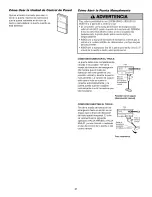
Страница 69: ... de la puerta paraabrirla cerrarla Si el nudo de la cuerda se suelta usted podria caerse COMO DESCONECTAR EL TROLE La puerta debe estar completamente cerrada si es posibte Tire de la manija de liberacion de emergencia de manera que et brazo de liberacion del trole quede en una posicion vertical y levante ta puerta manualmente La funcion de seguro evita que et trole se vuelva a conectar automa tica...

Страница 70: ...dicionat No lubrique los carriles de la puerta LA BATER A DEL CONTROL REMOTO Paraevitar la posibilidad de LESIONESGRAVESo incluso LA MUERTE NUNCApermita que los niSos pequeSosest_n cerca de las baterias Si alguien se traga una bateria Ilame al m_dico de inmediato Para reducir el riesgo de incendio explosi6n o combusti6n quimica ReemplaceUNICAMENTEcon baterias planas 3V2032 NOrecargue desarme calie...

Страница 71: ... los limites det recorrido y repita la prueba de retroceso de seguridad Es normal tener que ajustar la fuerza y los limites det recorrido peri6dicamente Las condiciones atmosfericas pueden afectar al recorrido de la puerta Consutte et apartado Ajustes Paso 1 Ajuste los Ifmites del recorrido hacia ARRIBA y hacia ABAJO Reduzca el recorrido hacia abajo girando et tornitlo de ajuste en sentido horario...

Страница 72: ...endida conecte la cetuta receptora Atinee los sensores Si las luces indicadoras se encienden sustituya los cables de los sensores Si las luces de los sensores no se encienden sustituya los sensores de seguridad _ Sintoma El LED del control de la puerta no se enciende Inspeccione la unidad de control de la puerta cabte para ver si tienen un cortocircuito grapa clavada en et cable y sustituya Io que...

Страница 73: ...l Motor Para desactivar cualquier control remoto que _lI_l i no desee usar antes que nada borre todos los codigos Oprima y mantenga oprimido el boton Aprender de la unidad del motor hasta que la luz det indicador de Aprender se apague aproximadamente 6 segundos Ya estara n borrados todos los odigos anteriores Vuelva a programar cada uno de los controles remotos o la entrada sin Ilave que desee usa...

Страница 74: ...ral expira y no vuetve a abrir la puerta Se puede usar para cerrar ta puerta aQn despues de que haya expirado Haga Io siguiente para poner un PIN temporal 1 Optima los cuatro botones correspondientes a su PIN de entrada personal no et Qltimo PIN temporal luego optima y mantenga oprimido et boton La luz det abridor va a parpadear tres veces Suelte et boton 2 Optima los cuatro digitos det PIN tempor...

Страница 75: ...ones de su abridor de puerta de cochera seran sin costo para usted si el abridor tiene defectos en materiales o mano de obra GARANT A LIMITADA Desde e dia 91 hasta 1 aflo a partir de la fecha de compra partes de repuestos seran proveidas si el abridor tiene defectos en materiales sin costo Usted paga la mano de obra GARANT A LIMITADA DEL MOTOR Desde el dia 91 hasta 4 afios si el motor del abridor ...

Страница 76: ...vacuums lawn equipment and electronics call anytime for the location of your nearest Sears Parts Repair Service Center 1 800 488 1222 U S A 1 800 469 4663 Canada www sears com www sears ca To purchase a protection agreement on a product serviced by Sears 1 800 827 6655 U S A 1 800 361 6665 Canada Para pedir servicio de reparaci6n a domicilio y para ordenar piezas 1 888 SU HOGAR 1 888 784 6427 www ...

Отзывы: