background image

Содержание 115.244500

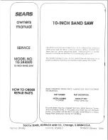
Страница 1: ...odel and serial numbers may be found on the back of the saw You should record both model and serial number in a safe place for future use FOR YOU SAFETY READ ALL INSTRUCTIONS CAREFULLY assembly o operating repair paffs J Sold by SEARS ROEBUCK AND CO Chicago IL 60684 U SoA Part No SP5492 printed in Taiwan ...

Страница 2: ...G OR MOVING THE SAW AVOID DANGEROUS ENVIRONMENT Use the saw in a dry indoor place protected from rain Keep work area well lighted To avoid injury from unexpected saw movement Put the saw on a firm level surface where there is plenty of room for handling and properly support ing the workpiece Support the saw so the table is level and the saw does not rock o Bolt the saw to the support surface if it...

Страница 3: ...GHT TOOL Don t force tool or attachment to do a job it was not designed to do Use this band saw to cut only wood wood like products and plastics Dress for safety WEAR YOUR _ _ I Any power saw can throw foreign objects into the eyes This can cause permanent eye damage Wear safety goggles not glasses that comply with ANSI Z87 1 shown on package Everyday eyegiasses have only impact resistant lenses T...

Страница 4: ...LEAVING THE SAW W _Hfor aHr t ovin parts to stoo Make workshop cr_ild proo_ Lock the shop Dmcor nect m _ste_ switc _es Remove the yellow sw tch key Sto_e _ta_ vay from chi drer_ a _d others not quatiSed to t se ti_e re hi g ossary of terms for woodworking Beveling An angle cutting ope_atim_ through the _ace of the board Crosscu_ A cutting operation made across the width of the workpiece Compound C...

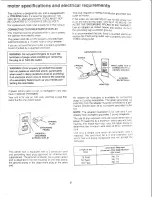
Страница 5: ...recommended that you have a qualified electrician replace the TWO prong outlet with a property grounded THREE prong outiet GROUNDING LUG SCREW iI i C oo o 2 PRONG _ X RECEPTACLE k ADAPTER if power cord is worn or cut or damaged in any way have it replaced immediately Your unit is for use on I20 volts and has a plug that looks like the one shown below i _ _ tt t PLUG ti P oNe _LT__ _ _ PROPERLY GRO...

Страница 6: ... o so Rtithe MEDIUM SCREWDRIVER 2 PHILLtPS SCREWDRIVER COMB N TtONSQUAREMUST BE TRUE _AW Lt_HT STRAIGHT EDGE OF LINE ON _ARD BOARD 314 THICK SH4_JLD BE NO GAP OR OVERLAP HERE WHEN _UARE tS FLtPPED OVER tN DOTTED POSi T1ON WARNING To avoid injury from unexpected staring or electrical shock do not plug the saw in unlil all assemMy and alignment steps are complete The power cord must remain unplugged...

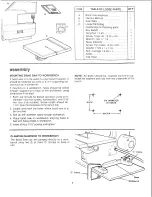
Страница 7: ...ace of the workbench using dimensions illustrated 1 Each leg should be bolted secureiy using 5 t6 diameter machine screws tockwashers and 5 16 hex nuts not included Screw length should be 1 3 4 plus the thickness of the bench top 2 Locate and mark the holes where band saw is to be mounted 3 Drill 4 3 8 diameter holes through workbench 4 Place band saw on workbench aligning holes in feet with holes...

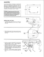
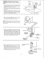
Страница 8: ...k Knob 24 MIN 6 5 16 _ 10 13 16 iNSTALLiNG THE TABLE 1 Loosen the upper slide lock knob ano position the upper guide assembly al of the way uo Tighten lock knob Upper Guide Assembly 2 Ouen the front cover of the saw oy pulling forward on the finger hold located on the left side of the band saw l Finger Hold 3 Locate the square hole behind the lower right wheel and insert a 1 4 20 x 1 tong carriage...

Страница 9: ...tion of the guides during opera tion of the saw Guide 5 Loosen the setscrew which locks the upper blade guide support located on the left side of the sup port behind the bearing Push the support all the way back Loosen the setscrew holding the upper back up bearing Located on the right side of the upper slide Push the bearing all the way back With the guide support and back up bearing pushed back ...

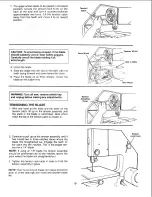
Страница 10: ...remove switch key and unplug before making any adjustments TENSIONING THE BLADE 1 With one hand on the knob and the other on the tension catch lift up on the tension assembly until the slack ir the blade _s eliminated Note which notch the top of the tension catch is closest to Tension Adjustin Knob 2 Continue to pull up on the tension assembly until it has moved two or three notches above where th...

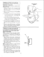
Страница 11: ...es Readjust if necessary until blade is tracking properly WARNING Turn off saw remove switch key and unplug before making any adjustments 1 ADJUSTING THE BLADE GUIDES AND BACK UP BEARING NOTE The upper and lower blade guides and back up bearings support the band saw blade during cut ting operations The adjustment of the guides and bearings should be checked whenever a different blade is installed ...

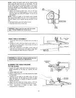
Страница 12: ...f the band saw ano snap _n place 2 Locate a 1 4 20 x 5 8 truss head screw and a 1 4 20 wing nut in _oose parts Insert screw into hole n table top as i_tustrated 3 From the underside of the table install w_ng nut onto the truss head screw and tighten finger tight This will keep the table flat and in alignment J WARNING Turn off saw remove switch key and unplug before making any adjustments ALiGNiNG...

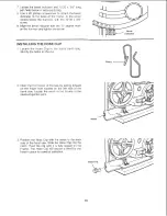
Страница 13: ...SE CUP 1 Locate the Hose Clip in the loose parts bag Identify the barbs on the clip Barbs 2 Open the front cover of the saw by pulling forward on the finger hold located on the left side of the band saw Locate the notch in the Frame at the sawdust ejection port Notch 3 Position the Hose Clip with the barbs to the back side of the band saw Slide the Hose Clip into the notch Push the clip until it i...

Страница 14: ...e cutting Always adjust the upper guide assembly and lock the upper slide by tightening the upper slide lock knob before turning on the band saw 3 TabJe lock knob Loosening the knob allows the table to be tilted and tightening the knob locks the table in place Bevel indicator 3 Table Lock Knob 4 Tilt bevel scale Shows degree taole is tilted for bevel cutting 5 Tension Lock Knob controls the amount...

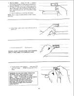
Страница 15: ...der switch lever and pulq end of switch out c To turn machine OFF PUSH lever in f_ NEVER LEAVE THE MACHINE UNATTENDED UNTIL _T HAS COME TO A COMPLETE STOP d To lock switch in OFF position hold switch IN with one hand REMOVE key with other hand WARNING For your own safety a ways lock the switch OFF when machine is not in use remove key and keep i_in a safe place also in the event of a power failure...

Страница 16: ...tal blade contact minimize blade breakage aria provide maximum blade support always adjust tne upper blade guide and blade guard to just clear the workpiece KEEP WORK AREA CLEAN Cluttered areas and benches _nvite accidents Floor must not be slip pery To avoid burns or other fire damage never use the saw near flammable iquids vapors or gases PJan ahead to protect your eyes hands face ears KNOW tOUR...

Страница 17: ...positions where a sudden slip could cause fingers or hand to move into the blade DON T OVERREACH Keep good Iooting and balance WHENEVER SAW _S F_U_N NG WARNING Don t let _amiHa_itY gai_led from freq_ent use o_ yo_Jr ba_d _ aw cause a care _ less mistake A ca_e_e _s fraction of a second is erlough to cause a severe injury L Beloro ar_ _ _ c _ watch the sa _ _ while it runs f it c _f makes a_ u_q_ m...

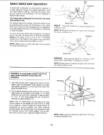
Страница 18: ...t hand removed for c_anty of o_cture only Workpiece Pattern Line Blade WRONG Not planning ahead for cutting a curve could bind or twist blade if workpiece is forced NOTE Blade guard is raised and right hand removed for clarity of picture only WARNING To avoid blade contact adjust the upper guide assembly lo just clear the workpiece 1 Use both hands while feeding the work into the blade Hold the wo...

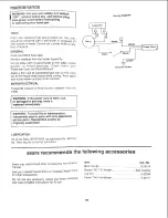
Страница 19: ...de surfaces of the trunnion MOTOR ELECTRQCAL Frequently vacuum or blow out any sawdust from the motor Wiring O_agt ar_ L eiack ___Green Ground Screw WARNBNG ff the power cord is worn cut or damaged in any way have it replaced immediately WARNING To avoid fire or e_ec_rocation reassemb0e eBectric parts with only approved service parts ReassembSe exactly as originally assembled LUBRICATION Alt of th...

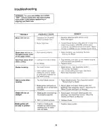
Страница 20: ...usted 2 Worn or defective blade 1 Patch on blade guide threads has deteriorated allowing them to rotate with the blade REMEDY 1 Rep ace defective parts before using Band Saw again Consult Sears Service Any attempt to repair this motor may create a HAZARD unless repa4r is done by a qualified service technician Repair service is available at your nearest Sears Store 1 Adjust tracking see Assemb y Se...

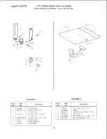
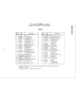
Страница 21: ...820279 82O281 7 820284 Description Guard Biade Scr Pan HD TY TT 10 32 x 3 8 Sc_ Soc Set 12 Dog Pt 1420 x 12 Scr Soc Set 1 4 20 _4 Suport Guide Sha_ w Bearing Slide Upper FIGURE 2 No j __ No I 60530 I 2 1817935 3 820874 4 817915 5 815865 2 6 817149 Description Scr Truss 1 4 20 58 Table Nut Wing Low Profile 4 L Trunnion Scr Hx Hd TYTT 14 20 x 8 Scr Locking Set 1 4 20 21 ...

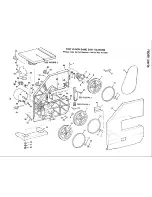
Страница 22: ...4O 44 42 35 33 I I 32 31 4O 19 18 FOR 10 INCH BAND SAW 113 244500 Always order by Part Number Not by Key Number 45 26 22 15 4 13 10 6 11 f mm I 1 ...

Страница 23: ...x 1 16 Foot Frame Screw Hex Hd 1 4 20 x 3 4 Lockwasher Int N 0 Nut Hex 0 32 Bolt Crge 1 4 20xl 1 Stock Item May Be Secured Through The Hardware Catalog Order Houses Standard Hardware Item May Be Purchased Locally Key No 25 26 27 28 29 30 31 32 33 34 35 36 37 38 39 40 41 42 43 44 45 46 Part NO STD502502 820272 STD532525 820088 817944 STD511103 820493 816464 813989 1 STD375006 820273 9 22256 816113 ...

Страница 24: ...be found on a plate located on the back of the Band Saw below the motor WHEN ORDERING REPAIR PARTS ALWAYS GIVE THE FOLLOWING INFORMATION PARTNUMBER PARTDESCRIPTION MODEL NUMBER 113 244500 NAME OF ITEM 10 Inch Band Saw A l parts listed may be ordered from any Sears Service Center and most Sears stores if the parts you need are not stocked locally your order will be electronically transmitted to a S...

Отзывы: