background image

Содержание 113.206891

Страница 1: ... MOTOR Serial Number Model and serial number may be found on a plate attached to your base You should record both model and serial number in a safe place for future use CAUTION Read ALL iNSTRUCTiONS carefully 6 1 8 iNCH JOINTER PLANER assembly operating repair parts Sold by SEARS ROEBUCK AND CO Chicago _L 60684 U S A Part No 67095 Primed iN US A ...

Страница 2: ... Don t use power tools indamp or wet locations or party the accessories The use of improper acces expose them to rain Keepw0rkamawel lighted i sories may cause hazards Provide adequate surrounding workspace 19_ NEVER STAND ON TOOL i 7 KEEP CHILDREN AWAY Serious injury could occur if the tool is tipped or All visitors should be kept a safe distance from _ if the cutting tool is accidentally contact...

Страница 3: ...wedge screws are tight for jointer planer 9 PROTECTION EYES HANDS FACE EARS BODY a If any part of your jointer is malfunctioning has been damaged or broken such as the motor switch or other operating control a safety device or the power cord cease operating immediately until the particular part is properly repaired or replaced b Wear safety goggles that comply with ANSI Z87 1 and a face shield if ...

Страница 4: ...N 3 INCHES OR PLANING MATERIAL THINNE_ THAN 3 INCHES WEAR YOUR The operation of any power too_ can result in foreign objects being thrown into the eyes which can result in severe eye damage Always wear safety goggles complying with ANSl Z87 1 shown on Package before commencing power tool operation Safety Goggles are available at Sears retail or catalog stores m _ _ contents POWER TOOL GUARANTEE 2 ...

Страница 5: ...to 2 prong receptacles The green grounding lug extending from the adapter must be con nected to a permanent ground such as to a properly grounded outlet box A temporary adapter as illustrated is available for con necting plugs to 2 prong receptacles The temporary adapter should be used only until a properly grounded outlet can be installed by a qualified electrician GROUNDING LUG _ _ _ _ _ LIJ 2 P...

Страница 6: ...hold type grease and spot remover WARNING Never use gasoline naptha or similar highly volatile solvents Apply a Coat of paste wax to the table Wipe all parts thoroughly with a clean dry cloth WARNING FOR YOUR OWN SAFETY NEVER CONNECT PLUG TO POWER SOURCE OUTLET UNTIL ALL ASSEMBLY STEPS ARE COMPLETE AI_D YOU HAVE READ AND UNDERSTAND THE SAFETY AND OPERA C 5 32 Setscrew Wrench i D 1 8 Setscrew Wrenc...

Страница 7: ...owing Hardware 40 Truss Head Screws 1 4 20 x 518 40 Lockwashers 4 External 40 Hex Nuts 114 20 8 Hex Nuts t 2 13 4 Leveling Feet 1 Assemble two 2 Side Stiffeners together using four 4 1 4 20 Truss head screws Iockwasher and nuts Make two 2 Side Stiffener assemblies The End Stiffeners are placed on top and at each end of Side Stiffener assemblies as shown Align holes letter coded B see page 8 in Sid...

Страница 8: ...AND SCREWS TOOLS NEEDED 5i32 and 118 Setscrew Wrenches furnished with 5 32 IN SETSCREW OUTFEED TABLE WRENCH i J inter Lead Pencii Short straight edge or head of Combination square i i ____ _ WEDGE i 1 Insert penci in space at end of cutterhead to hold L k I __ cutterhead guard open _ _______ _ 2 Lower the infeed table wilth the Depth of Cut Hand wheel 3 Rest the straight edge on edge on the surfac...

Страница 9: ...es marked X in motor mounting bracket DO NOT TIGHTEN BOLTS AT THIS TIME The L bracket which holds the guard support must be slid between the motor base and the motor mounting 3 Slide long teg of L bracket between motor base and motor mounting brackeL Then sandwich the short leg of the L bracket between the guard support bracket and the guard support and loosely fasten together with self threading ...

Страница 10: ...D II iiiii lUll II II IH PULLEYS AND V BELT I MUST BE STRAIGHT IN LINE __ AT 90 WITH RELATIONSHIP _ _ __ TO THE FLOOR 1 _V BELT GUARDS REMOVED _ ___ __ _ _ FOR PICTURE CLARITY MOTOR _i_ _r i _ _ STRAIGHT LINE J _ I UP DOWN 9o_ m I I 2 Hex Nuts 1 4 20 1 Rex Nut 1 2 in 13 1 Split iockwasher 1 2 in 2 Ext tooth Iockwashers 2 Sliding Guard Washers one side of washer is concave 2HeX Hd Screws 1 4 2Ox 2 ...

Страница 11: ...ing to know your jointer planer WARNING FOR YOUR OWN SAFETY TURN SWITCH OFF AND REMOVE PLUG FROM POWER SOURCE OUTLET BEFORE MAKING ANY ADJUSTMENTS FENCE TILT SCALE BEHIND FENCE 2 FENCE LOCK KNOB FENCE OUTFEED TABLE 2 SLIDING GUARD KNOB BACK OF JOINTER 5 INFEED TABLE Ii SLtDE BRACKET F O TOF JOINTER 4 CUTTER GUARD 6 ON OFF DEPTH OF CUT SWITCH 1HANDWHEEL DEPTH OF CUT HANDWHEEL Tu_rning the hand whee...

Страница 12: ... tables To tilt fence loosen the fence lock knob and sliding lock knob and pull the stop out Tilt to desired angle and tighten both knobs d e To set fence at 90 to tables loosen the two knobs tilt fence so the stop springs back into place Tilt fence back so the stop rests on the table and tighten both knobs 45 Fence Stop positions the fence at 45 to the tables SL D G GUARD KNOB PUSH DOWN _ _ __ WH...

Страница 13: ...t if it was adjusted for 90 position FENCE HEAD OF SQUARE CUTTER GUARD NFEED TABLE i i ll AUXILIARY FENCE Some on edge and other jointing operations require a higher and or longer fence than your tool provides Select a piece of smooth straight wood of the height and length required for proper support and bolt itto the tool fence as shown for these operations 1 4 20 FLAT HEAD J SCREW _COUNTERSL at ...

Страница 14: ...ge square or long level on outfeed table First along oneside than along the other c Raise infeed table until it touches straightedge d Sight between table and straightedge to determine high or tow condition of end of infeed table PENCIL OUTFEED TABLE 111 iiiii i iiii 111 i iiiiiiiiiiiiiii ROTATE BLADE OUT OF WAY It is easier to adjust the infeed table whi ethe Jointe r is setting on your workbench...

Страница 15: ...ICATION Turning the LEVELING STUDS will RAISE or LOWER the infeed table SCREWING in the studs will RAISE the table UNSCREWING them will LOWER the table a With a 3 4 in wrench turn levering studs until infeed table is parallel with straightedge b While holding studs with wrench TIGHTEN all four LOCKSCREWS tighten each screw a little bit at a time until all four screws are tight c Recheck with strai...

Страница 16: ...i i i i ll KEY NOTE Key is made of yellow plastic b To turn machine on insert finger under switch lever and pull end of switch out l II IIIIII II I l lHll I I IIIIIIIIIIII IUIJIIU c TO turn machine OFF PUSH lever in Never leaVe machine unattended until it has come to a complete stop JLLIU_IjtJ III I I III i ii ii ii J J i ii ii iiii i i lUlUll d To lock switch inOFF position hold switch 1N with on...

Страница 17: ...AtNST the fence keep fingers cfose together Feed the board at a continuous even rate of speed until the cut is made along the entire length of the board Any hesitation or stopping could cause a step to be cut on the edge of the board which would causethe board to ride up on the outfeed table resulting in a crooked edge on ___ _ __ _ the board JOINTING WOOD THAT IS WIDER THAN 3 IN i i i1 1 111 ll m...

Страница 18: ...also be sufficient to prevent hold down push block sliding or slipping on the top face of workpiece when advancing workpiece over cutter head Use a hand over hand motion of the hold down push blocks being careful to maintain Control over the workpiece at all times This means that once the workpiece has been fed past cutter head ontooutfeed table one hold down push block must always maintain contac...

Страница 19: ... INCHES CHAMFER BEVEL BEVELING BOARD NARROWER THAN 3 INCHES NOTE Rabbeting on a Jointer is considered to be a dangerous operation because it requires removal of the cutter guard and increases the potential of kickback because of excessive depth of cut NEVER ATTEMPT TO PERFORM A RABBETING OPERA TION ON THIS JOINTER DO NOT OPERATE JOINTERi PLANER WITH CUTTERHEAD OR BELT GUARDS REMOVED Rabbet cuts sh...

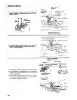
Страница 20: ...ulley firmly with one hand gently pry up each wedge using a screwdriver remove wedges and blades 7 Remove the six lifter screws Two under each blade 8 Clean cutterhead wedges and screws thoroughly with Craftsman Gum and Pitch Remover also remove the oil from new blades SETSCREW 5 32 IN WRENCH BLADE LIFTER WEDGE LOCKSCREW _L_ J _ t CUTrER HEAD SETSCREW 9 Replace the six lifter screws and screw them...

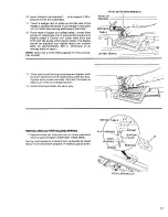
Страница 21: ...ximately 003 in thickness of an average piece of paper NOTE Sears has a knife setting gauge for this purpose Cat 9 2647 1 8 IN SETSCREW WRENCH HEAD OF SQUARE LIFTER SCREW ii 1111 iiii 13 Now install both locking setscrews and tighten with the 5 32 setscrew wrench alternately a little at a time Tighten both screws securely Recheck the blade to make sure it did not change position 14 Install other t...

Страница 22: ... NEVER ROTATE GUARD BE 0NDI POSI_ TION B BECAUSE THIS WOULD EXERT EXCESSIVE _ TENSION ON SPRING WHICH COULD WEAKEN OR_ POSITION A BREAK IT Check operation of GUARD and SPRING 1 With fence in MAXIMUM WIDTH OF CUT position pass a piece of 1 4 in thick wood on edge jointing position over cutterhead 2 The guard should return automatically to its REST position against the fence when free of the wood 3 ...

Страница 23: ...the motor Do not allow pitch to accumulate on the tables the fence Do not allow chips to accumulate on the underside of the jointer planer Frequently blow out any dust that may accumulate inside the motor If power cord is worn or cut or damaged in any way have the cutter guard the cutter head or the knives Clean them with Craftsman Gum and Pitch Remover Apply a thin coat of paste type wax to the t...

Страница 24: ...UR JOINTERPLANER TROUBLE SHOOTING CHART TROUBLE PROBABLE CAUSE REMEDY Motor will not run 1 Defective On Off switch i i Replace defective parts before using machine again Defective switch cord Defective switch box receptacle 2 Motor protector open ionly if your motor is equipped _ With an overload ProteCtor Other Cause i Wood strikes ouffeed Blades improperly adjusted table after passing over below...

Страница 25: ...otor due to sawdust accumulating inside of motor 1 Burned switch contacts due to extended hold in periods caused by low line voltage etc 2 Shorted capacitor 3 Loose or broken connections 1 Starting switch not operating 2 Voltage too tow to permit motor to reach operating speed 3 Fuses or circuit breakers do not have sufficient capacity 1 Motor overloaded 2 Fuses or circuit breakers do not have suf...

Страница 26: ...47 9 11 52 51 50 44 16 40 37 36 15 4 1 12 23 24 25 48 FIGURE 1 54 55 56 35 32 27 22 26 i ...

Страница 27: ...l 113 206932 Motor See Fig 6 Supplied with Modet 113 206891 Wrench Hex 1 8 Wrench Hex 5 32 Key Part No No 30 STD522512 31 63410 32 67016 33 STD541031 34 102832 35 67017 36 STD551025 37 STD551125 38 STD551150 39 120238 40 21638 41 18516 42 STD551131 43 STD523117 44 21733 45 60078 46 STD580025 47 21636 48 37158 49 67062 50 67021 51 21237 52 132275 53 21450 54 18112 55 80116 56 21632 57 60117 56 6011...

Страница 28: ...russ Hd 1 4 20 x 5 8 e Lockwasher 1 4 External e Nut Hex 1 4 20 Stiffener Side Leg e Clip Cord Support Motor e Nut Hex Hal 1 2 13 Foot Leveling Bag of Loose Parts Not lltus HARDWARE FOR MOUNTING TOOL AND MOTOR STD532507 STD55123I STD551031 STD523120 STD541231 e Bolt Carriage 5116 18 x 3 4 e Lockwasher 5 16 External e Washer 11 32 x 11 16 x 1 16 e Screw Hex Hd 5 16 18 x 2 e Nut Hex 5 16 18 28 _ i i...

Страница 29: ...e Plate Screw Pan Hd 10 32 x 7 8 Lockwasher No 10 Washer No 10 Spring Guard Plate Support Bushing Screw Cap 1 4 20 x 1 2 Hex Hd Washer Plain 17164 Plate Tension Key No Part No 13 21422 14 21219 15 21218 16 STD551131 17 21635 18 STD523112 19 STD55 031 20 2 204 2 STD54t025 22 STD551125 23 STD522510 Description Spacer Dovetail Dovetail Male Dovetail Female Lockwasher 5 16 Screw Spl Screw Cap 5 16 I8 ...

Страница 30: ...rchased Locally 111 I I f ill l I I III I I li l IIIIIIIIIIIIIIIIIIlill IIIIIIIIIIIJl Key Part No No 10 STD551210 11 STD511102 12 67009 13 STD533725 14 21738 15 STD551037 16 47624 17 62331 I I FtGURE 5 ON OFF POWER OUTLET 60381 5 6 Key No Description Lockwasher Ext 10 Screw Mach No 10 32 x 1 4 Pn Hd Slotted Guard Cutter Bolt Carriage 3 8 16 x 2 1 2 Round Head Retainer Bolt Washer 13 32 x 13 16 x 1...

Страница 31: ... the end of the GREEN wire of power cord with ockwasher between terminal and motor frame See illus 3 Reinsert GREEN SCREW in the threaded hole Tighten securely 4 Insert te rminat end of WHITE wire on spade terminal marked T4 on the motor Push terminal firmly until seated 5 Insert terminal end of BLACK wire on spade terminal marked T1 on the motor Push terminal firmly until seated 6 Close motor con...

Страница 32: ... The model number of your 6 1 8 inch jointer planer will be found on a plate attached to your base WHEN ORDERING REPAIR PARTS ALWAYS GIVE THE FOLLOWING INFORMATION PART NUMBER PART DESCRIPTION MODEL NUMBER 1t 3 206801 113 206932 113 206891 NAME OF ITEM 6 1 8 INCH JOINTER PLANER All parts listed may be ordered from any Sears Service Center and most Sears stores If the parts you need are not stocked...

Отзывы: