background image

Содержание 113.20680

Страница 1: ...d to your infeed table You should record both model and serial number in a safe place for future use CAUTION Read GENERAL and ADDITIONAL SAFETY INSTRUCTIONS carefully CRRFTSMRNo 6_ INCH JOIN TER PLA NER assembly o operating e repair parts Sold by SEARS ROEBUCK AND CO Chicago IL 60684 U SA Part No 67018 ...

Страница 2: ...RONMENT the accessories The use of improper accessories may Don t use power tools in damp or wet locations or cause hazards expose them to _r_ain Keep work area well lighted Provide adequate surrounding work space _ z19_ NEVER STAND ON TOOL 7 k l l P r_l lllr_Rl l_i _ Serious in ur cou d occur f the too ti if the WAY j y is pped or cutting too s accidentally contacted All visitors should 5ekept a ...

Страница 3: ...ke sure the cutter blades are in stalled properly and cutter blade wedge screws are tight 9 PROTECTION EYES HANDS FACE EARS BODY a If any part of your jointer is malfunctioning has been damaged or broken such as the motor switch or other operating control a safety device or the power cord cease operating immediately until the particular part is properly repaired or replaced b Wear safety goggles t...

Страница 4: ...ER THAN 1 16 INCH ALWAYS USE HOLD DOWN PUSH BLOCKS FOR JOINTING MATERIAL NARROWER THAN 3 iNCHES OR PLANING MATERIAL THINNER THAN 3 INCHES The operation of any power tool can result in foreign objects being thrown into the eyes which can result in severe eye damage Always wear safety goggles complying with ANSI Z87 1 shown on Package before commencing power tool operation Safety Goggles are availab...

Страница 5: ... by Underwriters Laboratories and the Canadian Standards Association The ground conductor has a green jacket and is attached to the tool housing at one end and to the ground prong in the attachment piug at the other end This plug requires a mating 3 conductor grounded type outlet as shown If the outlet you are planning to use for this power toot is of the two prong type DO NOT REMOVE OR ALTER THE ...

Страница 6: ...r CAUTION Never use gasoline na_ha or similar highly volatile solvents Wipe all parts thoroughly with a clean cloth Apply a coat of automobile wax to the tables and fence This will help prevent rust and make it easier to feed the work while planing 3 4 1 Qty 1 Jointer Planer 1 12 i V Belt li2x 52 IV Belt 1 2 x 37 1 3 5 32 Setscrew Wrench 1 4 1 8 Setscrew Wrench 1 5 Motor Pulley 2 1 2 Dia 1 6 Slidi...

Страница 7: ... on handwheel attach with 1 1 4 in screw i i i nl i i CHECKING CUTTER BLADES AND SCREWS TOOLS NEEDED 5 32 and 1 8 Setscrew Wrenches furnished with Jointer Lead Pencil Short straight edge or head of combination square 1 Insert pencil in space at end of cutterhead to hold cutterhead guard open 2 Lower the infeed table with the Depth of Cut HandwheeL 3 Rest the straight edge on edge on the surface of...

Страница 8: ... side DOWN on support rod 5 Drop sliding guard onto rod place other washer con cave side UP on rod screw on Sliding Guard Knob SLIDING GUARD KNOB 10 32xl 4 SCREWS EXT TOOTH LOCKWASH ERS WASHER CONCAVE SIDE UP MOUNTING RECOMMENDED CRAFTSMAN MOTOR AND BELT GUARDS See page 5 for recommended motors PARTS NEEDED 4 carriage bolts 5 16 18 x 1 in flat washers lock washers and nuts supplied with Craftsman ...

Страница 9: ...d outlet See page 5 Notice rotation of pulley If it is not turning COUNTERCLOCKWISE REMOVE plug from outlet and change rotation of motor accord ing to instructions furnished with motor WARNING FOR YOUR OWN SAFETY MAKE SURE PLUG IS NOT CONNECTED TO POWER SOURCE OUT LET WHEN CHANGING ROTATION 5 32 IN SETSCREW WRENCH DIRECTION OF ROTATION FLUSH HERE MOTOR SHAFT KEY 1 Insert carriage bolts through hol...

Страница 10: ...bly 6 Install three clips on belt guard 90 apart with long tabs pointing AWAY from round opening 7 Insert belt into open end of guard BELT _ _ BELT GUARD CLIPS 90 APART 8 Snap guard into position as shown 10 ...

Страница 11: ... to tension the belt so that it does not slip while running If you cannot obtain sufficient tension with motor push ed all the way down remove the four motor bolts and insert them in LOWER set of holes NOTE To remove guard lift up on LONG TABS of clips pull guard outward The clips should remain on BELT GUARD SUPPORT JOINTER PULLEY BELT GUARD INSTALLATION 1 Attach guard to stand with Hex Hd screws ...

Страница 12: ...FENCE TILT SCALE BEHIND FENCE FENCE LOCK KNOB FENCE OUTFEED TABLE 2 SLIDING GUARD KNOB 1NFEED TABLE l SLIDE BRACKET 4 CUTTER GUARD ON OFF SWITCH DEPTH OF CUT HANDWHEEL I DEPTH OF CUT HAN DW H EEL i _ Turning the handwheet counterclockwise will lower the infeed table to maximum depthof i 8 in 12 INFEED DEPTH OF CUT TABLE HANDWHEEL UP DOWN ...

Страница 13: ...e two knobs and pull the stop out Tilt to desired angle and tighten both knobs d e To set fence at 90 to tables loosen the two knobs tilt fence so the stop springs back into place Tilt fence back so the stop rests on the table and tighten both knobs 45 Fence Stop positions the fence at 45 to the tables f To tilt fence to 45 loosen the two knobs pull 90 stop out tilt fence so the 45 stop rests on t...

Страница 14: ...d adjust fence square to table 45 o ST KNURLED _ SLEEVE_ _ 90 o STOPS C d_ Tighten 90 stop Iockscrew and both fence lock knobs If 90 reading on tilt scale does not line up with top surface of the slide bracket loosen screws holding scale and move it tighten screws SCALE ADJUSTING _ SCREW oc sc Ew t_l_ II V_ _ ADJUSTING SCREW BRAC KE T e Adjust 45 stop in the same manner NOTE Tilt scale wilt not re...

Страница 15: ...d does not return automatically see Trouble Shooting and Maintenance Sections CUTTER GUARD FENCE INFEED TABLE _ INFEEDTABLE MUST ALWAYS BE PARAL LEL TO THE OUTFEED TABLE If the cut edge or surface of the workpiece is CROWNED it is an indication that the OUTWARD END of the INFEED table is HIGH and must be adjusted If the cut edge or surface of the workpiece is CON CAVE it is an indication that the ...

Страница 16: ...pside down to adjust it Attach a stripof wood to two blocks of wood 10 in high Drive enough nails into the strip so that Jointer does not tip over while resting on blocks i t a Remove motor cord from outlet in switch box b Remove joir_ter pulley guard and V belt c Remove Jointer from stand d Lower theinfeed table e Place Jointe_ioh biocksill _ _ i _i_ I ii i___i _i _ii _ _ i _i _L II I _ 10 IN BLO...

Страница 17: ...ime until all four screws are tight c Recheck with straightedge to make sure infeed table is parallel to outfeed table ill 6 ON OFF SWITCH It is untikely that it will be turned ON accidentally when touched or bumped because of the way it is shaped In an emergency it can be turned OFF by striking it with the palm of the hand The yellow button is a key When inserted in the switch lever the power may...

Страница 18: ...r hand WARNI NG FOR YOUR OWN SAFETY ALWAYS LOCK THE SWITCH OFF WHEN MACHINE IS NOT IN USE REMOVE KEY AND KEEPIT IN A SAFE PLACE ALSO IN THE EVENT OF A POWER FAILURE ALL OF YOUR LIGHTS GO OUT TURN SWITCH OFF AND REMOVE THE KEY THIS WILL PREVENT THE MACHINE FROM STARTING UP AGAIN WHEN THE POWER COMES BACK ON PULL e Plug motor cord into outlet in switch box WARNi NG DON T CONNECT POWER CORD TO ELECTR...

Страница 19: ... the fence keep fingers close together Feed the board at a continuous even rate of speed until the cut is made along the entire length of the board Any hesitation or stopping could cause a step to be cut on the edge of the board which would cause the board to ride up on the outfeed table resulting in a crooked edge on the board JOINTING WOOD THAT IS WIDER THAN 3 IN As the RIGHT hand passes over th...

Страница 20: ...top of workpiece and push the workpiece down against the table to provide a quality cut and minimize the chance of a kickback Hold down pressure must also be sufficient to prevent hold down push block sliding or slipping on the top lace of workpiece when advancing workpiece over cutter head Use a hand over hand motion of the hold down push blocks being careful to maintain control over the work pie...

Страница 21: ...made with one cut therefore a cut deeper than 1 t6 in may be made Use hold down push blocks for wood under 3 in wide Position them so you have control of the workpiece at all times and so they do not contact the guard or the c_tter head CHAMFER BEVEL NOTE Rabbeting on a Jointer is considered to be a dangerous operation because it requires removal of the cutter guard and increases the potential of ...

Страница 22: ...uard and fence 5 Hold cutterhead pulley firmly with one hand and loosen lockscrews in each wedge using a 5 32 in setscrew wrench 5 32 iN SETSCREW WRENCH HOLD PULLEY FIRMLY TURN COUNTER CLOCKWISE BLADE WEDGE LI FTER LOCKSCREW SCREW FENCE NOT SHOWN FOR PICTURE CLARITY 6 While holding cutterhead pulley firmly with one hand gently pry up each wedge using a screwdriver re move wedgesand blades I 1 SMAL...

Страница 23: ...not install two locking setscrews at this time t2 _ Place head of square on outfeed table Loosen lifter screws to raise blade until it just touches square and slightly raises it Gently turn cutter head back and forth with the pulley while raising blade The blades should be adjusted just slightly above the outfeed table by approximately 003 in thickness of an average piece of paper NOTE Sears has a...

Страница 24: ... SCREW feed table it will not perform properly if installed upside down i i VIEW LOOKING UP FENCE IN PLACE CUTTER GUARD 1 Position guard asshown with PIVOT PIN above hole in infeed table 2 Align SLOT in pin with TANG in spring and press down 3 Replace cotter pin _OL _ IN _INFEED TABLE PIVOTPIN r i 4 RAISE end of FENCE rotate guard COUNTER clockwise only enough to CLEAR fence 5 LOWER fence and tigh...

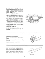
Страница 25: ...here are no burrs rust or other foreign matter 4 Apply a few drops of SAE No 20 or No 30 engine oil to pivot pin 5 Replace guard and cotter pin If guard still does not return to its REST position con suit your local Sears Retail Store before using3 the jointer planer POSITION A WIDTH OF CUT 1 SHARPENING CUTTER BLADES The blades can be honed individually with an ordinary oilstone Make sure your oil...

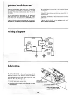
Страница 26: ...hem with Craftsman Gum and Pitch Remover with motor Apply a thin coat of automobile type wax to the tables and fence so that the wood slides easily while feeding If power cord is worn or cut or damaged in any way have it replaced immediately wiring diagram E _ MOTOR WHITE _ OUTLET 11 SWITCH Cap Flag J L I _ _ Terminal I m m m m lubrication The BALL BEARINGS in this machine are packed with greaseat...

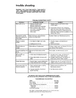
Страница 27: ...her t Re adjust blades see Maintenance section 2 Feeding wood too fast 2 Feed wood slower l l i i i i i H ii Infeed table out of adjustment Re adjust infeed table see Getting To Know your Jointer Planer section Blades set too high above outfeed Reset blades see Maintenance section table 1 uu w i 1 Fence stops not adjusted properly 1 Re adjust fence stops see Getting To Know your Jointer PJaner sec...

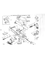
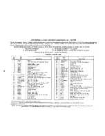
Страница 28: ... 1NCH JOINTER PLAN E R MODE L NO 113 20680 INFEED TABLE SEE FIGURE 2 FOR EXPLODED VIEW 47 47 I t i FENCE ASSEMBLY 2 SEE FIGURE 3 FOR EXPLODED VIEW 3 5 36 37 SWITCH BOX ASSEMBLY SEE FIGURE 4 FOR EXPLODED VIEW 30 31 12 33 34 26 12 10 9 11 17 21 S ...

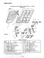
Страница 29: ... Groove 5 8 Bore Keyed Guard Belt Motor Screw Ty 23 Pan 10 32 x t 2 Support Belt Guard Bracket Support Clip S Wrench Hex I 8 Wrench Hex 5 32 Screw Much 1 4 20 x 1 4 Truss Hd w Lockwasher Knob 3 1 4 Shaft Elevating Key Part No No 27 STD 54103i 28 102832 29 67017 30 21638 31 120238 32 STD 551150 33 STD 551125 34 STD 551025 35 18516 36 STD 551131 37 STD 523117 38 STD 551210 39 21733 40 60078 4t STD 5...

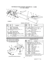
Страница 30: ... Hd 10 32 x 7 8 Lockwasher No 10 t Washer No 10 Standard Hardware ltems_ M_y B e PUtchasedI_o_lly_ FIGURE 2 PARTS LIST No 13 14 15 16 17 18 19 20 2t 22 23 Part No 21422 21219 21218 STD551131 21635 STD523t t2 STD55103 t 21204 STD541025 STD551125 STD522510 Description Spacer Dovetail Dovetail Male Dovetail Female Washer Split Lock 5 16 Screw SpI _Screw Cap 5 16 18 x 1 1 4 Hex Hd Washer 5 16 Linkage ...

Страница 31: ...Bolt Carriage 3 8 16 x 2 t 2 Round Head Retainer Bolt Washer 35 64 I D Spacer Knob Assembty Lock i i i ii i i i i i i i i i i iii 1 i iii 67024 SWITCH BOX ASM DOMESTIC FIGURE 4 PARTS LIST 67025 SWITCH BOX ASM CANADIAN NOTE Above assemblies do not include Key No 10 Order separately if needed 1 2 1 12 11 4 F1GURE 4 Key Part No _ No 1 STD54t110 2 STD551210 3 STD601103 4 60269 5 62376 6 60267 7 60317 ...

Страница 32: ... 8 inch jointer planer will be found on a plate attached to your infeed table WHEN ORDERING REPAIR PARTS ALWAYS GIVE THE FOLLOWING INFORMATION PART NUMBER MODEL NUMBER 113 20680 PART DESCRIPTION NAME OF ITEM 6 1 8 INCH JOINTER PLANER All parts listed may be ordered from any Sears Service Center and most Sears stores If the parts you need are not stocked locally your order wilt be electronically tr...

Отзывы: