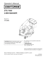
background image

Содержание 107.24906

Страница 1: ... For answers to your questions about this product call 1 800 659 5917 Sears Craftsman Help Line 5 am 5 pm Mon Sat Nota Una traducci6n en espa5ol de este Manual del Operador puede encontrarse en la pagina 11 Sears Roebuck and Co Hoffman Estates IL 60179 U S A Visit our Craftsman website www sears com craftsman 1732542 01 Revision Date 04 2006 TP 199 4278 01 AT C ...

Страница 2: ...igence including but not limited to failure to maintain the equipment according to the instructions contained in the operator s manual Bagger if used for commercial or rental purposes WARRANTY SERVICE IS AVAILABLE BY RETURNING DEFECTIVE PARTS TO THE NEAREST SEARS PARTS REPAIR CENTER IN THE UNITED STATES FOR THE NEAREST SEARS PARTS REPAIR CENTER LOCATION CALL 1 800 4 MY HOME This warranty gives you...

Страница 3: ...r the chute with a piece of wood before restarting the engine NEVER place hands into COLLECTOR OR MOWER housing to clear jammed objects MOWER may rotate when object is removed For added stability and to prevent tipping or loss of control a Use reduced speed on uneven ground and when turning corners b Reduce loads on hillsides it is recommended that the collection system be kept only half full when...

Страница 4: ... of 32 Ibs is required when using this rear mounted grass catcher Never operate mower on slopes greater than 10 AFTER OPERATION Remove any debris from the the screen on the underside of the hopper lid Note The lid screen can be partially removed for easier cleaning and should be cleaned regu larly The discharge tubes should be removed for cleaning _ WARNING Inspect the grass bags for wear or hole ...

Страница 5: ...Y RULES 1 Never operate mower on slopes greater than 10 2 Front counter weight is required when ever using rear mounted grass collection system 3 Always remove counterweight before removing mower Figure 2 Remove Carriage Bolt A Bracket and Mower Deck Housing B Locknut 5 16 18 C Carriage Bolt 5 16 18 5 8 Figure 1 Install Mounting Plate A Pin B Front Counter Weight C Safety Clip D Mower Hitch INSTAL...

Страница 6: ...Secure with 3 8 16 x 1 3 8 capscrews E washers I washers C and nut D as shown Finger tighten at this time 2 Install 1 2 13 x 1 1 4 capscrew G through drawbar H and tighten 3 Tighten all hardware Bag Support installation 1 Set bag support tube B Figure 5 onto hitch assem bly post D 2 insert bag support posts A into hitch assembly tubes C Make sure that support posts insert com pletely into tubes Fi...

Страница 7: ... E Figure 7 2 Place the front hole of the lower chute A onto car riage bolt C as shown Slide front edge of lower chute A under hinge bracket G 3 Place the rear hole of the lower chute A onto car riage bolt F as shown 4 Secure knob B onto carriage bolt C as shown 5 Secure wing nut D onto carriage bolt F as shown Connecting Upper Middle Tube 1 Slide lower tube A Figure 8 into upper tube B Figure 7 I...

Страница 8: ...so that bracket C rests in support D Pull rubber loop strap B over upper tube and secure into notch A 2 Slide middle tube assembly E Figure 9 onto lower tube F 3 Slide middle tube F over lower tube I Pull rubber strap H and place hole completely over pin G Figure 11 Bag Installation A Bag Support Hoops B Bag Hoops C Bag D White Bar Bag Installation t Install bag C Figure t t with white bar C towar...

Страница 9: ...er tube M under hinge bracket G Place the rear hole of the lower tube M onto car riage bolt 0 as shown Secure knob Q onto car riage bolt P Secure wing nut W onto carriage bolt 0 4 Slide middle tube T into upper tube L and sent into support K Secure with rubber loop strap J by hooking it into slot S 5 Slide middle tube T over lower tube M Pull strap N and place hole completely over pin V WARNING OP...

Страница 10: ...10 ...

Страница 11: ...os motores Antes que arranque el motor lea y comprenda el Manual del Due5o IMPORTANT Lea y siga todas las reglas e intrucciones de seguridad antes de operar este equipo Para obtener respuestas a qualquier pregunta sobre este producto Ilame al num o de tel fono sin cobro siguiente 1 800 659 5917 Servicio de ayuda Sears Craftsman 5 am 5 pm Lunes a Sabado 11 ...

Страница 12: ...ntre otros no mantener el equipo conforme alas instrucciones comprendidas en el manual del propietado Emblosadora que se usa con fines comerciales o de alquiler EL SERVICIO DE GARANTIA EST _ DISPONIBLE Sl RETORNA EL RECOLECTOR DE CO SPED DE CRAFTSMAN AL CENTRO 0 DEPARTAMENTO DE SERVlCIO DE SEARS M _ SCERCANO A USTED EN LOS ESTADOS UNIDOS PARA AVERIGUAR CU _L ES EL SEARS M _S CERCANO A USTED LE ROG...

Страница 13: ... 4 Quite el objeto extraho o limpie el conducto con un pedazo de madera antes arrancar nuevamente el motor NUNCA ponga las manos en el RECOLECTOR O la caja de la PODADORA para quitar objetos atasca dos La PODADORA puede girar al quitar el objeto Para dar mayor estabilidad y evitar que se vuelque o perder el control a Uso una velocidad m s baja en terrenos desnivelados y al dar la vuelta en una esq...

Страница 14: ...e desconectar o desmontar el tubo o vaciar el recolector SlEMPRE apague la unidad Desacople el PTO y permita que se detengan todas las partes en movimiento ANTES de desconectar o desmontar el tubo o vaciar el recolector Antes de dejar el puesto del operador pot cualquier raz6n accione el freno de mano desacople el PTO detenga el motor y quite la Ilave Para reducir el peligro de un incendJo manteng...

Страница 15: ... sistema montado atr_ s de la colecci6n de la hierba 3 Quite siempre el contrapeso antes de quitar el cor tacespedes Figura 2 Quite el perno de carro A Bracket y la cubierta B Locknut perno de carro de 5 16 18 5 16 18 C Perno de Carro 5 16 18 5 8 Figure 1 Fronte Instalaci6n del contrapeso cortac_spedes demostrado de la unidad para el clarity A Pin B Contra peso para el Frente C Pin de Seguridad D ...

Страница 16: ... 16 x 1 3 8 E arandelas I arandelas C en la ordenen que se demuestra Apriete dot mano temporalmente 2 Instale el tornillo de cabeza hexagonal de 1 2 13 x 1 1 4 G pas_ ndolo pot la barra de enganche H y apri6telo 3 Apriete todos los componentes con herramientas Instalaci6n del Soporte para Saco 1 Coloque el tubo del soporte para saco B Figura 5 sobre el poste del sistema de enganche D 2 Inserte los...

Страница 17: ...l canal inclinado mas bajo A sobre el perno de carro C segOn Io demostrado Resbale el borde delantero de un canal inclJnadomas bajo A debajo del soporte de bisagra G 3 Ponga el agujero posterior del canal inclinado m_ s bajo A sobre el perno de carro F 4 Asegure la perilla B sobre el perno de carro C 5 Asegure la tuerca de ala D sobre el perno de carro F Conectar el tubo superior y medio de la dia...

Страница 18: ...or E en la soporte del bolso D de mode que la bracket C se recline en el soporte D Tire el lazo de la correa B goma y asegQrelo en la muesca a 2 Resbale el grdpo de tube medio E figura 9 sobre un tube m_ s bajo F 3 Resbale un tubo mas bajo F del excedente medio del tube I Tire de la correa de goma H y coloque el perno del excedente del agujero totalmente G 18 Figura 11 Instalaci6n del Saco A Aros ...

Страница 19: ...a G Ponga el agujero posterior del tubo mas bajo M sobre el perno de carro O Asegure la perilla Q sobre el perno de carro P Asegure la tuerca de ala W sobre el perno de carro O 4 Resbale el tubo medio T dentro del tubo superior L y enviado en la ayuda K Asegure con la correa de goma del lazo J enganchandola en la correa de goma de la ranura S 19 5 Resbale un tubo mas bajo T del excedente medio del...

Страница 20: ......

Страница 21: ...RepairParts PTS 1 ...

Страница 22: ...Chute Group ZTS 7500 2 Bin Bagger NOTE Unless noted otherwise use the standard hardware torque specification chart 1 I I I I 16 14 15 17 I 18 5 7 16 19 6 11 t i18 i I t i i 13 PTS 2 ...

Страница 23: ...achine 1 4 20 x 1 2 NUT Hex KEPS 1 4 20 Black 2 NUT Hex Flange Toplock Small 1 4 20 Black 1 STRAP Hood Rubber Black 1 HANDLE Connect Tube 1 PIN Latch 1 CARRIAGE BOLT 1 4 20 x 5 8 G5 Black 1 TUBE Boot Poly Black 1 NUT 5 16 18 Wingnut 2 CARRIAGE BOLT 5 16 18 x 3 4 G5 Black 4 SCREW Truss Head Torx Drive 5 16 18 x 7 8 Black 2 STRAP Bagger 42 Mower Black 4 NUT Hex Lock ESNA Light 5 16 18NC3B Black 1 KN...

Страница 24: ...ss noted otherwise use the standard hardware torque specification chart 5 _ J J g 8 1 Trap robber bandinto slot of seal plate with carriagebolt and nut i 20 I 15 17 32 18 8 33 34 39 1 I D Decal Location 4O 37 37_ 41 I 35 41 38 _ Rear 37 Weights 39 37 PTS 4 ...

Страница 25: ...Clear PVC WASHER 3 16 TOP Hopper Black Plastic SEAL Corner Black Rubber HINGE Hopper Top CAPSCREW Hex Flange Whiz Lock 1 4 20 x 3 4 SEAL Center Black Rubber NUT Hex Flange 1 4 20 ESNA STIFFENER Front Hopper STIFFENER Rear 24 13 16 Long LATCH Hopper SCREEN 1 4 Mesh 20 x 28 RETAINER Screen Nylon Push In Type WASHER 3 16 x 3 4 DECAL Warning Objects Thrown by Mower NUT Hex Flange 5 16 18 ESNA PIPE SHA...

Страница 26: ...3 1 2 20 9 16 12 9 16 18 5 8 11 5 8 18 3 4 10 3 4 16 7 8 9 7 8 14 1 8 1 12 in Ibs ft Ibs Nm 19 2 1 20 2 3 27 3 1 31 3 5 in Ibs ft Ibs Nm 30 3 4 31 3 5 43 4 9 49 5 5 in Ibs ft Ibs Nm 41 4 6 43 4 9 60 6 8 68 7 7 66 7 6 8 76 8 6 10 11 15 0 17 12 16 3 19 20 27 2 30 23 31 3 35 30 40 8 50 35 47 6 55 50 68 0 75 55 74 8 90 65 88 4 110 75 102 0 120 90 122 4 150 100 136 180 160 217 6 260 180 244 8 300 140 1...

Страница 27: ...on line for the location of your nearest Sears Parts Repair Center 1 800 488 1222 Call anytime day or night U S A only www seare conl To purchase a protection agreement U S A or maintenance agreement Canada on a product serviced by Sears 1 800 827 6655 U S A 1 800 361 6665 Canada Para pedir servicio de reparaci6n a domicilio y para ordenar piezas 1 888 SU HOGAR sM 1 888 784 6427 Au Canada pour ser...

Отзывы: