background image

page 12

Troubleshooting.

Warranty.

Problem: 

Fan fails to operate.

Solutions:

1. Check power to wall switch/wall control.
2. Verify that reverse switch is set completely in either direction.
3. Verify that receiver is wired properly.
4. Check to be sure fan is wired properly.
5. Verify wall control is wired properly.
6. Check to be sure code switches are set properly in remote 
control transmitter and wall control.
7. Learning process between fan, remote control transmitter 
and wall control may not have been successful and code was 
not activated. Turn off power and repeat instructions in last 
paragraph of Section 10 (page 10).
8. Check that red light on remote control transmitter turns on 
when a button is pressed indicating that the battery is good.

Problem: 

Light kit not lighting.

Solutions:

1. Check power to wall switch/wall control.
2. Check that bulbs are installed correctly.
3. Check that wires in canopy are wired properly.
4. Verify that molex connections in light kit fitter are connected 
properly.
5. Learning process between fan, remote control transmitter 
and wall control may not have been successful and code was 
not activated. Turn off power and repeat instructions in last 
paragraph of Section 10 (page 10).

Problem: 

Fan operates but light fails.

Solutions: 

1. Check that bulbs are installed correctly.
2. Check that wires in canopy are wired properly.
3. Replace defective bulb with same type of bulb.
4. Verify that molex connections in light kit fitter are connected 
properly.

Problem: 

Fan and light fail to operate with remote control.

Solutions:

1. Check battery power to remote control.
2. Check to be sure code switches are set properly in remote 
control transmitter and wall control.
3. Learning process between fan, remote control transmitter 
and wall control may not have been successful and code was 
not activated. Turn off power and repeat instructions in last 
paragraph of Section 10 (page 10).
4. Check for battery in wall control; verify battery is still good.

Problem: 

Lighting source (up-light, down-light or both) not 

functioning.

Solution:

Wattage Limiting Device has interrupted the flow of electricity 
to the light source. Ensure bulbs total no more than 190W in 
the light source. 

Problem: 

Fan wobbles.

Solutions:

1. Use the balancing kit in one of the hardware packs. 

If no 

blade balancing kit is provided, please call Customer Support, 
1-800-486-4892, to request one.

2. Check to be sure set screw(s) on motor housing yoke is (are) 
tightened securely.
3. Check to be sure set screw on hanging ball is tightened 
securely.

Parts Replacement.

WARNING: 

Failure to disconnect power supply 

prior to troubleshooting any wiring issues may 
result in serious injury.

CRAFTMADE/ELLINGTON LIFETIME LIMITED WARRANTY:
CRAFTMADE/ELLINGTON warrants this fan to the original 
household purchaser for indoor use under the following 
provisions:
1-YEAR WARRANTY: CRAFTMADE/ELLINGTON will replace 
or repair any fan which has faulty performance due to a 
defect in material or workmanship. Contact 
Craftmade/Ellington Customer Service at 

1-800-486-4892


to arrange for return of fan. Return fan, shipping prepaid, to 
Craftmade/Ellington. We will repair or ship you a 
replacement fan, and we will pay the return shipping cost.
5-YEAR WARRANTY: CRAFTMADE/ELLINGTON will repair or 
replace at no charge to the original purchaser any fan 
motor that fails to operate satisfactorily when failure 
results from normal use.
RETURN FAN MOTOR ONLY, shipping prepaid, to 
Craftmade/Ellington. We will repair or ship purchaser a 
replacement motor and Craftmade/Ellignton will pay the 
return shipping cost.
6 YEAR to LIFETIME LIMITED WARRANTY: 
CRAFTMADE/ELLINGTON will repair the fan, at no charge 
for labor only to the original purchaser, if the fan motor 
fails to operate satisfactorily when failure results from 
normal use. Parts used in the repair will be billed to the 
purchaser at prevailing prices at time of repair.
    The purchaser shall be responsible for all costs incurred 
in the removal, reinstallation and shipping of the product 
for repairs.
    This warranty does not apply when damage from 
mechanical, physical, electrical or water abuse results in 
causing the malfunction. Deterioration of finishes or other 
parts due to time or exposure to salt air is specifically 
exempted under this warranty.
    Neither Craftmade/Ellington nor the manufacturer will 
assume any liability resulting from improper installation or 
use of this product. In no case shall the company be liable 
for any consequential damages for breach of this, or any 
other warranty expressed or implied whatsoever. This 
limitation as to consequential damages shall not apply in 
states where prohibited.

For parts and information, please refer to
"Parts Inventory" on page 2.
Craftmade/Ellington Customer Support:

1-800-486-4892

www.craftmadebrands.com

Содержание MOR54ESP3

Страница 1: ... Remote Control Operation pg 11 Testing Your Fan pg 11 Troubleshooting pg 12 Warranty pg 12 Parts Replacement pg 12 PRINTED IN CHINA READ THESE INSTRUCTIONS AND SAVE THEM FOR FUTURE USE Installation Guide For Models MOR54ESP3 MOR54MWW3 net weight of fan 22 27 lb 10 1 kg Federal regulations require ceiling fans with light kits manufactured or imported after January 1 2009 to limit total wattage con...

Страница 2: ...ze wire connectors to use WARNING If using this fan in a DAMP location this fan must be connected to a supply circuit that is protected by a Ground Fault Circuit Interrupter GFCI to reduce the risk of personal injury electrical shock or death 5 Electrical diagrams are for reference only Light kits that are not packed with the fan must be CETL Canada or ETL USA listed and marked suitable for use wi...

Страница 3: ... for proper installation and safety a canopy 1 piece b hanging bracket pre attached to canopy 1 piece c downrod and hanging ball with pin and clip 1 piece d yoke cover 1 piece e motor housing 1 piece f wall control and plate 2 separate pieces g remote control receiver 1 piece h remote control transmitter and plate 2 separate pieces i light kit fitter 1 piece j glass shade 1 piece k safety cable wi...

Страница 4: ...isconnect power supply prior to installation may result in serious injury Remove existing fixture WARNING When using an existing outlet box be sure the outlet box is securely attached to the building structure and can support the full weight of the fan Ensure outlet box is clearly marked Suitable for Fan Support If not it must be replaced with an approved outlet box Failure to do so can result in ...

Страница 5: ...ical wires this will keep the wires together when threading them through the downrod Loosen yoke set screws and nut at top of motor housing Remove pin and clip from downrod if you have not already done so Slide downrod through canopy and yoke cover Thread safety cable and electrical wires through downrod and pull extra wire slack from the upper end of the downrod Refer to diagram 3 Thread downrod ...

Страница 6: ...int wood ceiling joist highly recommended and secure safety cable It will be necessary to use a heavy duty wood screw washer and lock washer not supplied with the safety cable loop Extra cable slack can be left in ceiling area Replace vice on safety cable and adjust safety cable length by loosening screw and nut on the safety cable vice and pulling on the cable Adjust slack in cable to a hands len...

Страница 7: ...ly circuit that is protected by a Ground Fault Circuit Interrupter GFCI to reduce the risk of personal injury electrical shock or death When downrod is secured in place on the hanging bracket wire the RECEIVER with wire connectors provided as shown in diagram at right Tip While you are wiring keep in mind that wires must not obstruct receiver from sliding into hanging bracket Wrap each wire connec...

Страница 8: ...e reasonable protection against harmful interference in a residential installation This equipment generates uses and can radiate radio frequency energy and if not installed and used in accordance with the instructions may cause harmful interference to radio communications However there is no guarantee that interference will not occur in a particular installation If this equipment does cause harmfu...

Страница 9: ...motor and partially loosen the other 2 screws Connect BLACK wire from motor housing to BLACK wire from light kit fitter Connect WHITE wire from motor housing to WHITE wire from light kit fitter Be sure that molex connections snap together completely NOTE It may be necessary to push back sleeve on wires to be certain of wire colors Be sure molex connections snap together securely Carefully arrange ...

Страница 10: ...o make sure glass is secured completely IMPORTANT When you need to replace the bulbs please allow decorative cage and glass shade to cool down before touching the bulbs Locate slots on outside light kit fitter and align with nodules inside decorative cage Gently push up on decorative cage and turn to the RIGHT clockwise until it slides completely into place Pull down gently on decorative cage to m...

Страница 11: ...labeled D and X has been pre set to the ON position D If you do not wish to have dimming capability please move the switch to the OFF position X Install one 12 volt battery included in transmitter Re attach battery cover on transmitter IMPORTANT Store the transmitter away from excess heat or humidity To prevent damage to transmitter remove the battery if not used for long periods Restore electrica...

Страница 12: ...rol do does not operate all of the fan functions refer to Troubleshooting section to solve any issues before contacting Customer Service Turn fan completely off before moving the reverse switch located on top of the motor housing diagram 1 Set reverse switch to recirculate air depending on the season LEFT position in summer diagram 2 RIGHT position in winter diagram 3 A ceiling fan will allow you ...

Страница 13: ...ancing kit is provided please call Customer Support 1 800 486 4892 to request one 2 Check to be sure set screw s on motor housing yoke is are tightened securely 3 Check to be sure set screw on hanging ball is tightened securely Parts Replacement WARNING Failure to disconnect power supply prior to troubleshooting any wiring issues may result in serious injury CRAFTMADE ELLINGTON LIFETIME LIMITED WA...

Страница 14: ... pared Pág 10 Funcionamiento del control remoto Pág 11 Verificación del funcionamiento del ventilador Pág 11 Localización de fallas Pág 12 Garantía Pág 12 Piezas de repuesto Pág 12 IMPRESO EN CHINA Guía de instalación Para modelos MOR54ESP3 MOR54MWW3 LEER ESTAS INSTRUCCIONES Y GUARDARLAS PARA UTILIZACION FUTURA El reglamento federal requiere que un ventilador de techo con juego de luz fabricado o ...

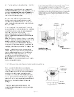
Страница 15: ...formarse sobre el tamaño correcto de conectores para cable que se debe usar ADVERTENCIA Si va a utilizar este ventilador en un lugar HÚMEDO hay que conectar el ventilador a un circuito de alimentación que esté protegido por un Interruptor de Circuito de Falla de Tierra GFCI por sus siglas en inglés para reducir el riesgo de daño corporal descarga eléctrica o la muerte 5 Los diagramas eléctricos so...

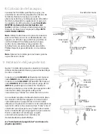
Страница 16: ...ue sirve para colgar con perno y clavija 1 unidad d cubierta del cuello 1 unidad e bastidor del motor 1 unidad f control de pared y placa 2 unidades distintas g receptor del control remoto 1 unidad h transmisor del control remoto y placa 2 unidades distintas i conectador para el juego de luz 1 unidad j pantalla de vidrio 1 unidad k cable de seguridad con seguro fijado de antemano al motor 1 unidad...

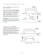
Страница 17: ...a instalación puede tener por resultado lesiones graves Quitar el aparato existente ADVERTENCIA Si utiliza una caja de salida existente asegurarse de que la caja de salida esté firmemente conectada a la estructura del edificio y que sea capaz de sostener el peso total del ventilador Asegurarse de que la caja de salida indique claramente que Sirve para ventilador FOR FAN SUPPORT si no se debe reemp...

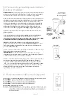
Страница 18: ... al pasarlos por el tubo Aflojar los tornillos de fijación del cuello y la tuerca en la parte superior del bastidor del motor Quitar el perno y la clavija del tubo si todavía no se hace Pasar el tubo por la cubierta decorativa y la cubierta del cuello Pasar los cables del ventilador y el cable de seguridad a través del tubo y con cuidado jalar el cableado en exceso por la parte de arriba del tubo ...

Страница 19: ...seguridad Utilizar tornillo para madera para trabajos pesados arandela y arandela de seguridad no provistos en el bucle del cable de seguridad Se puede poner el cable en exceso en el área del techo Volver a poner el seguro en el cable de seguridad y ajustar el largo del cable de seguridad aflojando el tornillo y la tuerca del seguro y jalando en el cable Ajustar la parte floja del cable para que m...

Страница 20: ...or un Interruptor de Circuito de Falla de Tierra GFCI por sus siglas en inglés para reducir el riesgo de daño corporal descarga eléctrica o la muerte Una vez que el ventilador esté bien sujeto en el soporte de montaje ALAMBRAR EL RECEPTOR con los conectores para cable provistos así como se muestra en el diagrama al lado Sugerencia Mientras está haciendo la instalación eléctrica recordar que los ca...

Страница 21: ...uerdo con la Parte 15 de las Reglas de la FCC Se concibieron estos límites para proveer protección razonable contra la interferencia adversa en una instalación residencial Este equipo produce usa y puede radiar energía de radiofrecuencia y si no se instala y no se usa según las instrucciones puede causar interferencia adversa en la radiocomunicación Sin embargo no hay ninguna garantía de que no ha...

Страница 22: ...luz conexión tipo molex aspa bastidor del motor tornillos y arandelas para fijar el aspa Quitar 1 tornillo de la placa de conexión en la parte inferior del bastidor del motor y parcialmente aflojar los otros 2 tornillos Conectar el cable NEGRO del bastidor del motor al cable NEGRO del conectador para el juego de luz Conectar el cable BLANCO del bastidor del motor al cable BLANCO del conectador par...

Страница 23: ...la agujas del reloj hasta que se encaje Con cuidado jalar hacia abajo en la pantalla de vidrio para asegurarse de que esté bien sujetada IMPORTANTE Cuando necesite reemplazar las bombillas favor de dejar que se enfríen la caja decorativa y la pantalla de vidrio antes de tocar las bombillas Localizar las ranuras en el exterior del conectador para el juego de luz y alinearlos con los nódulos dentro ...

Страница 24: ...er la capacidad de bajar la luz favor de mover el interruptor a la posición APAGADO X Instalar 1 batería de 12 voltios incluida en el transmisor Poner la tapa de la batería en el transmisor de nuevo IMPORTANTE Guardar el transmisor lejos del calor excesivo y la humedad Para prevenir daño al transmisor sacar la batería si no se va a utilizar el transmisor por un tiempo extendido Volver a conectar l...

Страница 25: ...nciones de ventilador y luz se ha instalado bien la batería en cado uno Si el ventilador y o la luz no funciona n favor de referirse a la sección Localización de fallas para resolver cualquier asunto antes de comunicarse con el Servicio al Cliente Apagar el ventilador completamente antes de mover el interruptor de reversa localizado en la parte superior del bastidor del motor diagrama 1 Regularlo ...

Страница 26: ...entilador se tambalea Soluciones 1 Usar el juego para balancear las aspas incluido en uno de los paquetes de artículos de ferretería Si no se incluye un juego para balancear las aspas llamar al Servicio al Cliente 1 800 486 4892 para pedir uno 2 Averiguar que se apretó apretaron bien el los tornillo s de fijación en el cuello del bastidor del motor 3 Averiguar que se apretó bien el tornillo de fij...

Отзывы: