4
Instruction and Operation Manual
Misprints and technical changes reserved
heat. If big masses have to be decelerated the braking resistor must have enough power related
to the kinetical energy.
The value of the brake resistor has to be equal or higher than R
min.
and depends
on the required output. If the brake resistor is lower than R
min.
, the IGBT (Insulated
Gate Bipolar Transistor) can be destroyed. The output is protected against short
circuit but not against permanent overload.
2.1
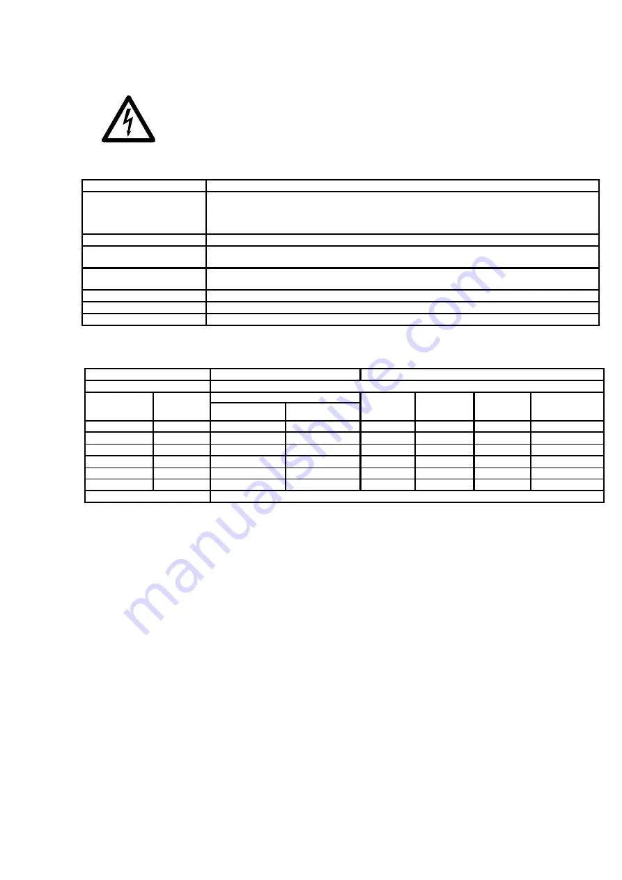
General data / application conditions
Range
Values
Permissible temperature range
During transport of the unit:
-
25°C…+70°C (to VDE 0160)
During storage of the unit:
-
25°C…+55°C (to VDE 0160)
During operation of the unit:
5°C…+40°C (without power derating)
40°C…+55°C (with power derating)
Humidity class
Humidity class F without condensation (5% - 85% relative humidity)
Environment:
Base standard:
DIN EN 60068-2-6
Resonance seach
Test specification:
(5 Hz-13,2 Hz)-150 Hz, 2mm peak to peak 0,7g
Installation height h:
H ≤ 1000 m a.m.s.l.
without power derating
1000 m a.m.s.l. < h 4000 m a.m.s.l.
with power derating
Air pressure
86kPa
–
106kPa to VDE0875 part 11 and prEN55082
Degree of pollution
VDE 0110 Part 2 degree 2
Enclosure:
IP20
2.2
Technical Data Chopper voltage 1000V
Connection voltage
500 - 1200 VDC
BUSS +/-
Power and Brake Resistor at Chopper voltage: 1000V
type
Article-No.
Brake power in kVA at
Permanent
current
[in A]
Peak current
[in A]
Superfast fuse
F2
[in A]
Brake resistor
>R
min
.
Permanent load
Peak load
BC 2.2-90/13
12272-0F
13
90
13
90
100
BC 3.2-90/58
12273-0F
58
90
58
90
100
11,2
BC 3.2-180/72
12273-2F
72
180
72
180
200
5,6
BC 4.2-300/90
12274-1F
95
300
95
300
355
3,4
BC 4.2-460/117
12274-2F
102
400
102
400
500
2,5
BC 4.2-490/110
12274-3F
112
500
112
500
500
2
Dimensions
refer to Chapter 5.


