background image

OPTIONAL SIDE DISCHARGE KITS

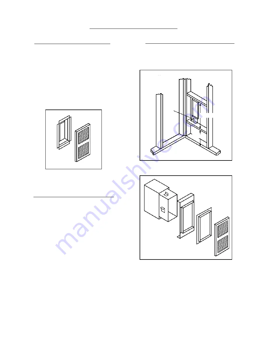
SIDE DISCHARGE ON CASING

1.

Use Optional Kit No. 306SR-A.

2.

Cut out and remove embossed area on casing side.

3.

Remove knockout from inner liner.

4.

Place 1-1/2” boot from kit through opening,
matching flanges of boot to knockout on inner liner.

5.

Mark screw holes and remove boot.

6.

Drill holes with a 1/8” drill.

7.

Attach inner boot with screws provided.

8.

Place grille into position, drill holes into casing,
and attach with screws provided.

SIDE DISCHARGE (With Extension Boot)

NOTE:  Maximum boot length is 10 inches.

1.

Use Optional Kit No. 30SRB-A.

2.

Cut opening in drywall as shown in Fig. 9.

3.

Position plaster ground as shown in Figure 9.
(Optional).

4.

Cut out and remove embossed section on casing side.

5.

Remove knockout on inner liner.

6.

Put heater into position.

7.

Place inner boot into position, mark and cut boot
flush with wall.  Place outer boot into position, mark
and cut boot flush with wall.

8.

Place boot trim into position, slide inner boot through
wall from adjacent room and attach to inner liner.
Slide outer boot through wall from adjacent room
and attach to casing side.

9.

Place grill in position and secure to wall.

ROUGH-INS FOR SIDE DISCHARGE

Install plaster grounds as shown in Figure 9.  NOTE:  When
side discharge Kit No. 30SRB is being used, furnace should be

set exactly 4” from side wall.

Plaster
Ground

10-3/

16”

14-3/8”

SIDE

FIGURE 9

KIT NO. 306SR
SIDE REGISTER - FLUSH

KIT NO. 30SRB
SIDE REGISTER W/BOOT

Page 14

Содержание DVCF403B-R and

Страница 1: ... without the properly installed furnished vent system and vent cap could result in Carbon Monoxide CO poisoning and possible death For your safety this furnace and the vent system should be inspected at least annually by a qualified service person This unit is not approved for installation in greenhouses or environments involving dusty wet corrosive or explosive conditions Such conditions will inv...

Страница 2: ...been removed from the carton check the rating plate to verify that the model number is correct and that the wall furnace is equipped with the type gas you intend to use The appliance may be installed in an aftermarket permanently located manufactured mobile home where not prohibited by local codes This appliance is only for use with the type of gas indicated on the rating plate This appliance is n...

Страница 3: ...nition 10 Young children should be carefully supervised when they are in the same room with the furnace 11 Do not place clothing or other flammable material on or near the furnace 12 Installation and repair should be done by a qualified service person The furnace should be inspected before use and at least annually by a professional service person More frequent cleaning may be required due to exce...

Страница 4: ...ly 3 Feet 91 cm within a height 15 Feet 4 5m above the meter assembly I Clearance to service regulator vent outlet 3 Feet 91 cm J Clearance to nonmechanical air supply inlet to building or the combustion air inlet to any other appliance 12 Inches 30 cm K Clearance to a mechanical air supply inlet 6 Feet 1 83 m L Clearance above paved sidewalk or paved driveway located on public property 7 Feet 2 1...

Страница 5: ...See Figure 2 7 RESIDENTIAL GARAGE INSTALLATION Gas utilization equipment in residential garages shall be installed so that all burners and burner ignition devices are located not less than 18 inches 46 cm above the floor Such equipment shall be located or protected so it is not subject to damage by a moving vehicle Use care in selecting a good location within the garage DO NOT locate the appliance...

Страница 6: ...window well or any other opening below ground level INSTALLATION ELECTRICAL ROUGH IN For convenience this furnace is equipped with a three prong power cord located on the top left of heater The 115V wiring should be brought in on the left side terminating in a receptacle box not provided Consult local codes or ordinances For Amps see Page 2 Specifications and Dimensions ROUGH IN GAS SUPPLY Install...

Страница 7: ... out Slide the vent cap onto the pipes extending from the back of the furnace A rotating or twisting motion will ease this installation Secure vent cap and vent cap spacer plate to wall causing the vent tubes to have a slight downward pitch This will prevent water from entering Anchors not provided may be required Caulk around vent cap spacer plate with caulking provided NOTE Some framing may be n...

Страница 8: ...ht to OFF 6 Wait five 5 minutes to clear out any gas Then smell for gas including near the floor If you smell gas STOP Follow B in the information on the safety label If you don t smell gas go to the next step 7 Open sight glass cover 8 Locate red piezo ignitor button on side of gas control Locate pilot behind sight glass Follow metal pilot tube from gas control 9 Slide gas control lever left to S...

Страница 9: ...nd any gas control which has been under water LIGHTING INSTRUCTIONS 1 STOP Read the information on the safety label 2 Set the thermostat to it s lowest setting 3 Turn off all electric power to the appliance 4 This appliance is equipped with an ignition device which automatically lights the pilot Do not try to light the pilot by hand 5 Remove cabinet door 6 Push in gas control lever slightly and sl...

Страница 10: ... needed PROPER BURNER FLAME The burner flame may be observed by raising the sight glass cover A proper flame will have a dark blue inner mantle that sits right on top of the burners with a lighter blue outer mantle rising above the burner See Figure 8 There may be some yellow where the pilot flame and burner flame meet There is no primary air adjustment on the burner and proper flame is assured si...

Страница 11: ...E BLACK BLACK RED RED BROWN BLACK TRANSFORMER GREEN WHITE WHITE BLACK BLACK BLACK BLACK BLACK GAS VALVE AUXILIARY LIMIT SWITCH BLUE BROWN LIMIT SWITCH FAN SWITCH SELECTOR SW BLACK DVCF653 DVCF654 PICTORIAL SCHEMATIC MODEL NO AMPS DVCF653 3 05 DVCF654 3 05 MOTOR FAN SWITCH LIMIT SWITCH 115 V A C 24 V A C TRANSFORMER THERMOSTAT AUXILIARY LIMIT GAS VALVE DVCF403 DVCF404 LADDER SCHEMATIC LIMIT SWITCH ...

Страница 12: ...TRANSFORMER LIMIT SWITCH FAN SWITCH Selector Sw Black BLACK BLACK BLACK BLACK BLACK AUXILIARY LIMIT SWITCH BLACK PILOT GAS VALVE P C M DVCF407 DVCF408 PICTORIAL SCHEMATIC DVCF557 DVCF558 PICTORIAL SCHEMATIC BLUE FAN SWITCH MOTOR LIMIT SWITCH THERMOSTAT 115 V A C 24 V A C TRANSFORMER SP715 NAT OR SP735 L P GAS VALVE DVCF407 DVCF408 LADDER SCHEMATIC MODEL NO AMPS DVCF407 2 2 DVCF408 2 25 MODEL NO AM...

Страница 13: ...th Do not use any kind of solvent or cleaning fluid that could leave a residue or invisible coating that would burn or give off fumes when furnace is turned on Have the furnace checked cleaned and repaired by a qualified service person for vent system pilot and burner operation prior to use each year The bearings of the fan motor should be oiled every twelve 12 months with S A E 20 oil See Figure ...

Страница 14: ...ion plaster ground as shown in Figure 9 Optional 4 Cut out and remove embossed section on casing side 5 Remove knockout on inner liner 6 Put heater into position 7 Place inner boot into position mark and cut boot flush with wall Place outer boot into position mark and cut boot flush with wall 8 Place boot trim into position slide inner boot through wall from adjacent room and attach to inner liner...

Страница 15: ...ions 8 Tighten two screws on romex connector 9 Replace junction box cover plate 10 Replace fan blade fan shroud and top louver assembly 11 Snap 90 degree outside corner Ref 1 onto 3 foot section Ref 2 plastic raceway Insert power cord and remove blue backing from adhesive strip on raceway and apply to side of heater 12 Insert power cord into second 3 foot section of raceway Ref 3 and remove blue b...

Страница 16: ... 1 Can be checked by removing wire from valve terminal or thermostat If valve goes off replace wire or thermostat 2 Thermostat location 2 Follow instructions check location 3 Defective or sticking valve 3 Replace valve 4 Excessive gas pressure 4 Contact utility supplying gas Incorrect gas input 1 Gas input not checked 1 Re check gas input 2 Clogged orifice 2 Clean orifice with a smooth wood toothp...

Страница 17: ...eed line 2 Defective thermocouple 2 Replace thermocouple Pilot won t light or 3 Pilot flame too low 3 Adjust pilot flame stay lit 4 Manual reset switch not engaged 4 Depress red button on switch I I D PILOT 1 Sparker won t work 1 Check wire connections provide adequate ground Pilot won t light 2 Sparker won t light pilot 2 a Pilot flame too small b Turn valve to on position c Check for pilot restr...

Страница 18: ...32 33 43 23 40 37 49 48 47 46 45 39 1g 51 1a 1f 1e 1d 24 1b 36 2 35 61 50 18 11 16 17 3 52 38 30 8 7 9 22 44 10 6 26 1c 4 19 21 20 Mr Contractor we only sell parts through our wholesalers but the prices listed are for your convenience For prompt parts service contact the wholesalerfromwhichyoupurchasedyourCozy heater NOTE Parts schematic drawings on current models are shown at www cozyheaters com ...

Страница 19: ...fice Natural Gas 15 72147 3 40 72147 3 40 72140 3 40 72142 3 40 Burner Orifice L P Gas 15 72149 3 40 72149 3 40 72141 3 40 72143 3 40 Fan Motor 16 72108 73 90 72108 73 90 72110 83 90 72110 83 90 Fan Blade 17 78101 24 20 78101 24 20 78101 24 20 78101 24 20 Rubber Grommet 18 78010 3 00 78010 3 00 78010 3 00 78010 3 00 Limit Switch 60T11 L220F 19 N A N A N A N A 72160 5 90 72160 5 90 Limit Switch 60T...

Страница 20: ...4 50 78070 104 50 N A N A Spark Igniter SP845 L P Gas 43 N A N A 78088 143 30 78088 143 30 N A N A Heat Exchanger Kit 44 34805 272 40 34805 272 40 34810 274 60 34825 285 60 Vent Cap Assembly Complete 45 34250 127 90 34250 127 90 34250 127 90 34250 127 90 Vent Cap Spacer Plate Assembly 46 34273 14 50 34273 14 50 34273 14 50 34273 14 50 Vent Cap Mounting Kit 47 34330 10 70 34330 10 70 34330 10 70 34...

Страница 21: ...r death IF YOU SMELL GAS DON T LIGHT IT IF YOU CAN T LIGHT IT DON T FIGHT IT THIS IS NOT AN ADVERTISEMENT WHAT TO DO IF YOU SMELL GAS Do not try to light any appliance Do not touch any electrical switch do not use any phone in your building Immediately call your gas supplier from a neighbor s phone Follow the gas supplier s instructions If you cannot reach your gas supplier call the fire departmen...

Страница 22: ... needed the user of the product shall request such service directly from the installer If the user is unable to locate the installer the user should write directly to the manufacturer and the name of an alternative service source will be supplied The product safety registration card packed inside the appliance must be completed and returned to the factory THIS WARRANTY IS EXPRESSLY IN LIEU OF ANY ...

Отзывы: