background image

EE

AA

C

Figure 6

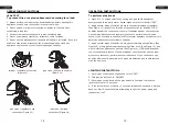
5. Insert three wide glasses (C) into the  "L" 

clips which have been welded together with 

table top, then attach them with bolts (AA) 

using the Phillips screwdriver (EE)

(See Figure 6).

Note:

 DO NOT tighten the bolts completely.

Note: 

 After the assembly is completed, the 

warning icon and font in the upper right 

corner of the glass should face outwards.

Hardware Used

Bolts (M6 X 5)  x 8 

AA

Phillips screwdriver  x 1

EE

Figure 5

4. Cover and clamp the four narrow glasses 

(D) with glass fixture (B) carefully. 

Afterwards, tighten the bolts (AA), but not 

tighten too much to avoid the glass pieces 

being damaged (See Figure 5).

B

D

Figure 4

Hardware Used

Bolts (M6 X 5)  x 8 

3. Insert the four narrow glasses (D) into 

the  "L" clips which have been welded 

together with table top, then attach them 

with bolts (AA) using the Phillips screwdriver 

(EE) (See Figure 4).

Note: 

DO NOT tighten the bolts completely.

D

E

EE

AA

AA

Phillips screwdriver  x 1

EE

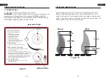
7. Place the gas cylinder into the 
cylinder holder. Secure the cylinder 
by tightening clockwise the retention 
point found on the cylinder holder, so 
that the cylinder cannot move from 
side to side or fall down. Connect 
the regulator, screw the black handle 
clockwise to tighten, turn the black 
handle counterclockwise to remove. 
The knob on the control panel is 
turned all the way to the “OFF” 
position when the heater is NOT in 
use (See Figure 8).

Figure 8

retention point

regulator

E

E

F

Figure 7

6. With the help of another person, cover and 

clamp the three wide glass (C) with metal 

shield (A) carefully and tenderly, insert the 

fourth wide glass (C) into the "L" clips in the 

metal shield (A) firstly, then insert the 

bottom of wide glass (C) into the "L" clips in 

the table top.

Note:

 tighten all the bolts but not 

overtighten to avoid the glass pieces being 

damaged.

Note: 

after assembly, the warning icon and 

font on the glass faces out and is located in 

the top right corner.

EE

C

Hardware Used

Bolts (M6 X 5)  x 8 

AA

A

Phillips screwdriver  x 1

EE

AA

ASSEMBLY INSTRUCTIONS

ASSEMBLY INSTRUCTIONS

14

15

Содержание NP10518US

Страница 1: ...era fournir une EXP RIENCE D ACHAT PRATIQUE des PRODUITS DE QUALIT et un SERVICE EFFICACE Con su calificaci n inspiradora COSTWAY ser m s consistente para ofrecerle EXPERIENCIA DE COMPRA F CIL BUENOS...

Страница 2: ...must be isolated from the gas supply piping system by closing its individual manual shutoff valve during any pressure testing of the gas supply piping system at test pressures equal to or less than 1...

Страница 3: ...er the cylinder is not in use Only install the type of dust cap on the cylinder valve that is provided with the cylinder valve Other types of caps or plugs may result in leakage of propane IMPORTANT S...

Страница 4: ...hromium hexavalent compounds AND BENZENE which are known to the State of California to cause cancer and birth defects or other reproductive harm For more information go to www P65warnings ca gov furni...

Страница 5: ...ment DANGER DANGER DANGER EXPLOSION FIRE HAZARD Keep solid combustibles such as building materials paper or cardboard a safe distance away from the heater as recommended by the instructions Provide ad...

Страница 6: ...propane cylinder outdoors in a well ventilated space out of reach of children Never store the propane cylinder in an enclosed area house garage etc If heater is to be stored indoors disconnect the pr...

Страница 7: ...ot attempt to assemble the product Tools Required for Assembly not included Phillips screwdriver PREPARATION WARNING WARNING SAFETY INFORMATION This product is fueled by propane gas Propane gas is inv...

Страница 8: ...s screwdriver x 1 EE 7 Place the gas cylinder into the cylinder holder Secure the cylinder by tightening clockwise the retention point found on the cylinder holder so that the cylinder cannot move fro...

Страница 9: ...NDIDO PARA CERRAR EL GAS 1 Presione ligeramente la perilla de control del gas y g rela a la 2 Gire la perilla de control del gas a ENC M N encendido m nimo 3 Presione la perilla de control del gas has...

Страница 10: ...new ones 1 Push in gas control knob slightly and turn to OFF 2 Turn gas control knob to ON MIN 3 Push in gas control knob all the way and hold Continue to press the ignition button for 15 seconds 4 If...

Страница 11: ...lightly and 2 Turn gas control knob to ON MIN 3 Push in gas control knob all the way 4 If the burner does not light in 15 1 Push in gas control knob slightly and turn to OFF TO TURN OFF GAS INSTRUCCIO...

Страница 12: ...en not in use to protect it from the elements NOTE Always allow patio heater to cool COMPLETELY before you cover the patio heater with an outdoor weather cover or you attempt to service or perform mai...

Отзывы: