6
4. ASSEMBLY INSTRUCTIONS
NOTE:
1. Gaskets shall be placed at both ends of the bolt (against bolt head and nut), as otherwise stated.
2. The initial assembly is to tighten all bolts and nuts by hand, and to tighten them with wrenches
when fully assembled.
3. Some spare parts have been pre-assembled in the factory.
4. This product is recommended for installation by more than two people.
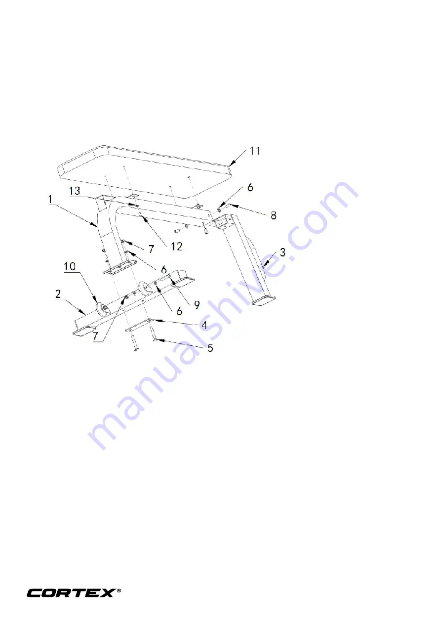
Step 1
1. According to the diagram, the 110 flat connection plate (# 4) is first installed under the ground
welding joint (# 2), then the carriage bolt M10 X70 (# 5) is connected to the main frame welding
joint (# 2) through the ground welding joint (# 2), and the flat gasket (# 6) and nut (# 7) are used to
fasten it.
2. Insert the post weld (# 3) into the main frame weld (# 1) as shown in the illustration and fasten it
with the inner socket head bolts M10 * 20 (# 8) and the flat gasket (# 6) on both sides and below.
3. Position the cushion (# 11) on the main frame weld (# 1) as shown and fasten it with the socket
head bolt M8 * 16 (# 12) and the flat washer (# 13).
4. According to the diagram, the rubber wheel is put into the ground welding joint (# 2) to get the two
welding sheets, and the inner hexagonal disc head bolt X 45 (# 9), flat gasket (#6) and nut (# 7)
are used to fasten it. Repeat the steps for the other side.
Please tighten the bolts and nuts with a wrench, your equipment is now fully assembled.
Содержание BN-7
Страница 5: ...5 3 PARTS LIST ...


