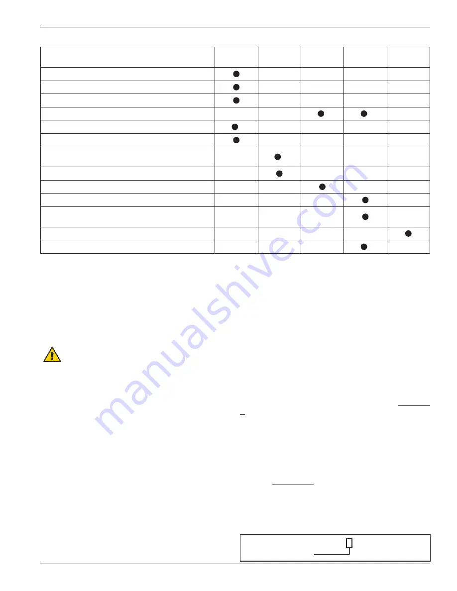
Item to Check
Daily
Weekly
Monthly
Six
Months
Yearly
Crankcase oil pressure
Compressor discharge pressure
Overall visual check
Crankcase oil level
1
1
Drain liquid from accumulation points
2
Drain distance pieces
Clean cooling surfaces on compressor and
intercooler (if any)
4
Lubricator supply tank level (if any)
Check belts for correct tension
Inspect valve assemblies
Lubricate motor bearings in accordance with
manufacturers’ recommendations
Inspect motor starter contact points
Inspect piston rings
1
3
Chapter 4—Routine Maintenance Chart
1
Change oil every 2,200 hours of operation or every 6 months, whichever occurs first. If the oil is unusually dirty, change it as often as needed to maintain a
clean oil condition. Change replacement filter 4225 with every oil change.
2
Liquid traps should be drained prior to startup.
3
Piston ring life varies greatly, depending on application, gas, and operating pressures. Consult factory for additional recommendations for a specific application.
4
Follow all safety precautions and use appropriate PPE (glasses, eye protection, special clothing, etc.) while cleaning. In particular, verify cooling fins are
cleaned regularly with a non-toxic, non-flammable, non-corrosive cleaning agent.
Chapter 5—Routine Service and
Repair Procedures
CAUTION: Always relieve pressure in the unit
before attempting any repairs . After repair,
the unit should be pressure tested and checked for
leaks at all joints and gasket surfaces .
If routine maintenance is performed as listed in chapter
4, repair service is generally limited to replacing
valves or piston rings. When it comes time to order
replacement parts, be sure to consult the part details
appendix in the back of this Installation, Operation &
Maintenance (IOM) manual for a complete list of part
numbers and descriptions.
5 .1 Compressor Valves
Test the compressor valves by closing the inlet piping valves
while the unit is running; however, do not allow the machine
to operate in this way very long. If the inlet pressure gauge
does not drop to zero almost immediately, one or more of the
compressor valves is probably damaged or dirty. However, it
is possible for the pressure gauge itself to be faulty.
In most cases, if a compressor valve or valve gasket
is leaking, it will create more heat. On a single stage
compressor, compare the operating temperatures of the
two suction or discharge valves and cover plates to each
other. If a valve or gasket is leaking, it will have a higher
operating temperature. NOTE: This method will not be
suitable for two stage compressors if each stage does
not have more than one valve.
Each suction and/or discharge valve assembly is easily
removed as a unit for inspection. If any part of the
valve assembly is broken, the valve assembly should be
replaced. See valve assembly parts details in the Appendix
D for a complete list of part numbers and descriptions.
If a compressor valve is leaking due to dirt or any other
foreign material that keeps the valve plate and seat from
sealing, the valve may be cleaned and reused. New gaskets
and/or O-rings should be used to ensure a good seal.
The valve holddown components and valve assemblies
listed in Appendix D show the various specifications
used on horizontal compressors. Since more than one
suction valve arrangement is available for each model of
compressor, it is necessary to know the complete model
number so the valve type specification number can be
identified (see example listed below).
Model number THG601BBGM 4 FBANSNNN
Valve type = spec 4
17


