Section 363-753-102
Revision 01
Page 5
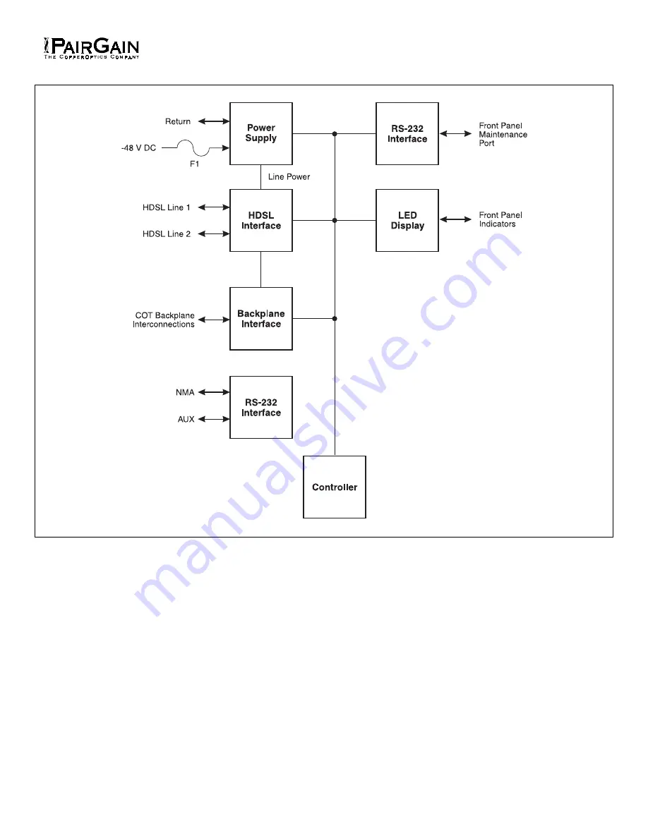
Figure 3. FRC-753 Block Diagram
Страница 1: ...TURES 2 2 APPLICATIONS 2 3 SPECIFICATIONS 3 4 CERTIFICATION 4 5 WARRANTY 4 B FUNCTIONAL DESCRIPTION 6 OPERATIONAL CAPABILITIES 6 7 FRONT PANEL 6 C INSTALLATION AND TEST 8 UNPACKING 6 9 TURN UP AND TES...
Страница 2: ...simplifies troubleshooting Pair Gain Test Controller PGTC Compatibility List 2 only 2 APPLICATIONS 2 01 Subscriber Drop Testing For subscriber drop testing from the central office PG Flex is able to...
Страница 3: ...le loop resistance minus 430 ohms for handset is 530 ohms RT Idle State Loop Voltage On Hook Greater than 40 Vdc Ring is negative with respect to Tip RT Loop Closure Off Hook Detection Less than 960 o...
Страница 4: ...the current edition of the National Electrical Code 5 WARRANTY 5 01 PairGain Technologies warrants this product to be free of defects and to be fully functional for a period of 5 years from the date o...
Страница 5: ...Section 363 753 102 Revision 01 Page 5 Figure 3 FRC 753 Block Diagram...
Страница 6: ...of the FRC 753 Channel Unit contains the following indicators see Figure 1 ACTIVE 1 8 LED Indicators Green the channel is off hook Flashing Green slow flash the channel is ringing the LED will track...
Страница 7: ...to bottom then turn off b After the system has powered up established HDSL synchronized communications and no calls are in progress observe the Channel Unit front panel indicators ACTIVE 1 off ACTIVE...
Страница 8: ...ts on the subscriber drop 2 If ringing isn t present on a circuit terminated on the same RT Channel Unit try ringing a line terminated on another RT Channel Unit If the line rings replace the RT Chann...