Section 363-712-100
Revision 02
Page 5
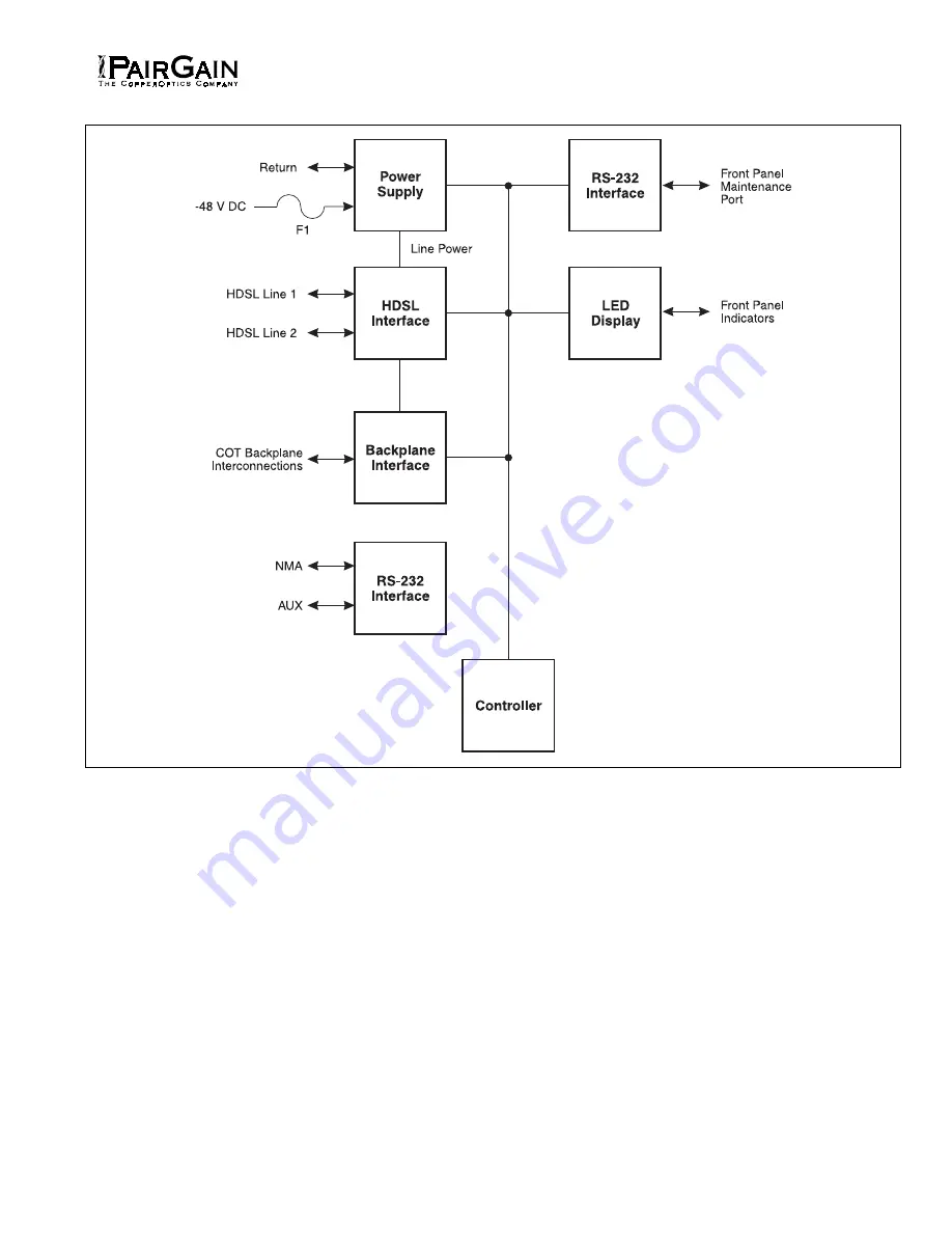
Figure 3. FLL-712 COT Line Unit Block Diagram.
Страница 1: ...2 2 APPLICATIONS 2 3 SPECIFICATIONS 3 4 CERTIFICATION 4 5 WARRANTY 4 B FUNCTIONAL DESCRIPTION 6 OPERATIONAL CAPABILITIES 4 7 FRONT PANEL 6 8 TERMINAL MANAGEMENT 7 C INSTALLATION AND TEST 9 UNPACKING...
Страница 2: ...A PG Flex system shown in Figure 2 consists of Central Office Terminal COT Two complete systems may be installed in a 19 inch COT Shelf and four complete systems may be installed in a 23 inch COT She...
Страница 3: ...criber line or to the test access bus 2 08 The test connection will be dropped when 116V is applied to the subscriber s COT tip for 1 5 seconds then removing the 116 V 2 09 Test access may also be act...
Страница 4: ...esentative will void the warranty 5 03 If a unit needs repair call PairGain for a Return Material Authorization RMA number and return the defective unit freight prepaid along with a brief description...
Страница 5: ...Section 363 712 100 Revision 02 Page 5 Figure 3 FLL 712 COT Line Unit Block Diagram...
Страница 6: ...line 1 margin is below a preset level Off HDSL line 1 margin is above the preset level LOOP 2 SYNC LED Indicator Green HDSL line 2 is in sync between the COT and RT Flashing Green HDSL line 2 is attem...
Страница 7: ...choose any of the following options Status Setup Test Inventory Status By selecting the Status option A from the Main Menu the technician can Display System Status to show the equipment installed in...
Страница 8: ...Section 363 712 100 Revision 02 Page 8 Figure 4 FLL 712 DB 9 Pin Outs A standard RS 232 DB 9 connector on the front panel provides access to the menu interface feature via a dumb terminal...
Страница 9: ...Section 363 712 100 Revision 02 Page 9 Figure 5 Terminal Menu and Display Structure...
Страница 10: ...s TABLE 2 FLL 712 COT LINE UNIT TURN UP AND TESTING CAUTION Observe normal electrostatic discharge precautions when handling electronic equipment Do not hold electronic plugs by their connector edges...
Страница 11: ...s a problem with the HDSL circuit between the COT and RT assuming the FAULT LED is off 2 COLU and RTLU incompatible That is one is a T1 version and the other is an E1 version a Verify the HDSL circuit...
Страница 12: ...re direct indication of the loop attenuation to the 2B1Q signal than the 196 kHz loss The normal range of pulse attenuation is from 1 to 32 dB PPM Indicates the relative offset of the crystal oscillat...