


5
CLUTCH REASSEMBLY
During reassembly of the clutch, all parts should receive a thin
coating of a mixture of 10W machine oil and NLGI 2-EP grease.
When installing the sear pin, No. 867909, the rounded end goes
into the clutch cam first. The sear plunger, No. 867886, goes into
the clutch cam cupped end first. All parts installed into the clutch
spindle and clutch cam, No. 867892, should be checked for
smooth operation before complete assembly of the clutch.
"H" RIGHT ANGLE HEAD ASSEMBLY
The driven gear and spindle ball bearing 847846, are pressed onto
the spindle shaft. Insert spindle shaft and gear into housing and
replace retainer ring No. 869033. Install the pinion gear and related
components into the rear of the angle head.
"K" RIGHT ANGLE HEAD ASSEMBLY
Slip pinion needle bearing, No. 869864, (unstamped end first) on
the pinion No. 202200, and press (press on the bearing's stamped
end) the bearing in to a depth of 7/8" from the face of the bearing
bore. Install pinion ball bearing, No. 847846 and bearing retainer,
No. 863564, in the head and tighten retainer securely using the 5/
8" hex nut and 5/8" deep socket. Using a suitable driver through the
hole in the top of the head, drive the pinion back to make sure it is
seated properly in the head.
"M" RIGHT ANGLE HEAD ASSEMBLY
Assemble the spindle and related components in the head and
securely tighten (left hand threads) the bearing cap, No. 864396.
Use bearing spacer, No. 869050, to press the pinion needle
bearing, No. 863360, (press on the bearing's stamped end) in the
head. Install ball bearing, No. 847846, and bearing retainer, No.
863564, in the head and tighten retainer securely using the 5/8"
hex nut and 5/8" deep socket.
TRIP ROD SIZING
A. Old Trip Rod
The tool should be reassembled complete less the trip rod, clutch,
and clutch housing. With the air on, install the trip rod and clutch
into the tool and measure the distance between the rear face of the
ball retainer, No. 867881, and the front face of the gear case. Turn
the air off and depress the clutch assembly and measure clutch
travel. Clutch travel must be at least 3/32". If not, the trip rod should
be replaced.
B. New Trip Rod
Assemble the tool completely, less the clutch housing, and con-
nect the tool to the air supply. Screw (left hand threads) the clutch
housing onto the gear case until air exhausts from the backhead.
Measure the gap between the clutch housing and gear case. Grind
this amount plus 5/64" minimum off the trip rod. IMPORTANT
NOTE: If the trip rod is too long the tool can ratchet or not shut off.
If the tool has a drop in power or RPM the trip rod can be to short.
Remember the trip rod length is not the only factor that causes
these problems. If you feel sure you have cut the trip rod length
properly look for other problems.
MOTOR DISASSEMBLY
Use a soft-faced hammer to drive the rotor out of the front rotor
bearing. This will allow the cylinder and four (4) rotor blades to be
removed from the rotor. Set the rear bearing plate on the vise jaws
with the rotor hanging down. Use a 7/32" punch to drive the rotor
out of the rear rotor bearing.
BACKHEAD DISASSEMBLY
Unscrew and remove the inlet bushing No. 202883, for inspection
and cleaning of the air inlet screen No. 833300. Replace the screen
if clogged or torn. Remove flow valve No. 203036, by removing
retainer ring No. 864271, then unscrewing flow valve with screw-
driver.
REASSEMBLY — GENERAL
All parts should be washed in a solvent and inspected for damage
or wear. Particular attention should be given to all bearings, gears,
gear pins, and rotor blades as failure of these parts could cause
damage to more expensive parts. Rotor blades should be replaced
if they measure less than 3/16" on either end.
Inspect and replace any "O"-rings or seals that show signs of wear
or deterioration. All gears, gear pins, and open bearings should
receive a generous amount of NLGI 2-EP grease during reassem-
bly.
Reassembly of all of the various subassemblies is in the reverse
order of disassembly; however, the following paragraphs list some
of the more important reassembly procedures.
MOTOR REASSEMBLY
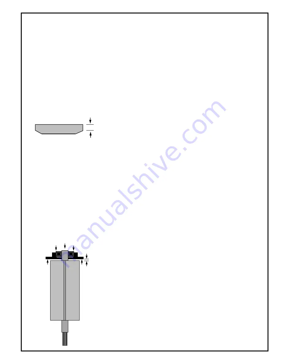
Assemble the rear rotor bearing and rear bearing plate (press on
the bearing's inner race) onto the rear rotor shaft until there is
approximately .0015" clearance between the plate and rotor.
Assemble the four (4) rotor blades, cylinder, front bearing plate,
and front rotor bearing (press on the bearing's inner race) to the
rotor assembly. After final assembly, the cylinder should be held
firmly, but not tightly between the two (2) bearing plates and the
rotor should turn freely and not rub either bearing plate.
Must be replaced if less than
3/16" (4.7mm) on either end.
.0015" (.038mm)
Clearance
Содержание Cleco 88 Series
Страница 22: ...22 NOTES...
Страница 23: ...23 NOTES...


