


6
MAINTENANCE
Periodically blow out all air passages with dry compressed
air. Remove wax and chip buildup from pulley tires and blade
guides. All plastic parts should be cleaned with a soft damp
cloth. NEVER use solvents to clean plastic parts. They could
possibly dissolve or otherwise damage the material.
SERVICE AND REPAIRS
All quality tools will eventually require servicing or replace-
ment of parts due to wear from normal use. Repairs should
be made by trained staff familiar with this product or by an
authorized Cleco Service Center. Original factory replace-
ment parts are recommended to maintain factory perfor-
mance specifications. If you have any questions about this
product, please contact your Cleco distributor or salesman.
DISASSEMBLY
BACKHEAD
The backhead 204212, can be separated from the handle
adapter 204206, by removing the retainer pin 204327. To
gain access to this pin, carefully roll the grip sleeve 204213,
back over itself beginning at the end adjacent to the handle
adapter, and until the pin becomes visible. Note: If "O"-rings
844311 and 847272 (2) two, are replaced, do not lubricate.
For inspection or replacement of the throttle valve or related
parts, unscrew the inlet bushing 204220. The air inlet screen
863598, should be washed in a solvent and blown out in the
reverse of normal air flow. Replace the screen if clogged or
torn.
HANDLE ADAPTER & UPPER HOUSING
The handle adapter and upper housing 204210 should not
be disassembled unless necessary. To disassemble handle
adapter from upper housing remove (3) three hex cap
screws 624820 and pull apart. To remove upper housing
from lower housing, remove (7) seven hex cap screws
204198 and pull apart.
LOWER HOUSING & INTERMEDIATE PLATE
To disassemble the lower housing 204211 from the interme-
diate plate 201655, remove (4) four hex cap screws 845758
and lift complete unit off the intermediate plate. The second-
ary muffler can be removed for inspection and motor can be
pulled out of lower housing. The primary muffler 204214
inside the lower housing can be removed from inside for
inspection.
MOTOR
Use a suitable driver to drive the front rotor shaft out of the
front rotor bearing. After removing the cylinder and rotor
blades, the rear rotor shaft may be driven out of the rear rotor
bearing.
REASSEMBLY
The tool is reassembled in the reverse order of disassembly.
Wash all parts in a solvent and inspect for damage or wear.
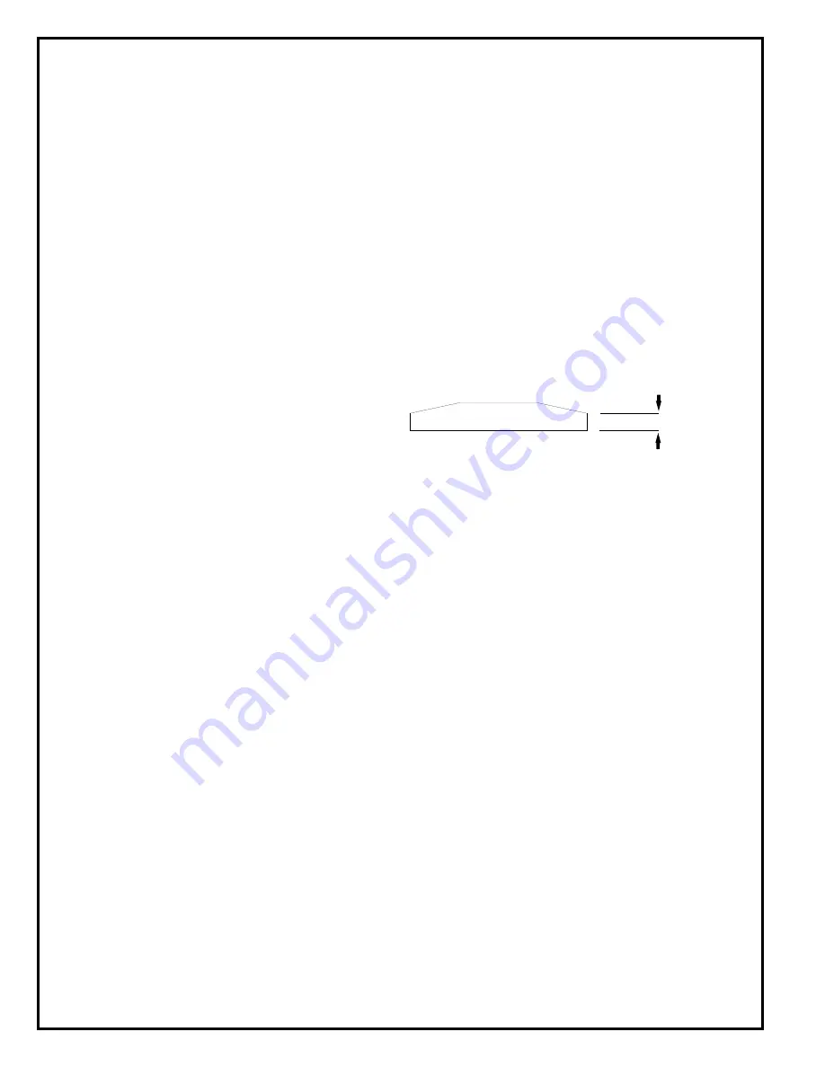
It is recommended that new rotor blades be installed at each
repair cycle. If not replaced, the used ones must measure a
minimum of 3/16" (4.7mm) at both ends.
Replace bearings that are rough or have excessive end play.
Install the front rotor bearing in the front bearing plate and
measure the distance from the face of the bearing plate to
the inner race of the bearing with the bearing race loaded
rearward. Select or fit by sanding, a rotor collar .001"
(.025mm) to .002" (.050mm) longer than this measurement.
Install the rotor blades, cylinder rear bearing plate, and rear
bearing on the rotor. After final assembly of the motor unit,
the cylinder should be held securely but not tightly between
the two plates. The rotor should not rub either plate.
Tighten all joints securely during reassembly. Place a few
drops of 10W machine oil in the air inlet to ensure positive
lubrication of all motor parts as soon as air is applied.
Replace if 3/16"
(4.7mm) or less
at either end.
Содержание CLECO 136 Series
Страница 7: ...7...
Страница 11: ...11 NOTES...


