


Page 3
KEY-EP
Fit External Prox Reader
Use M4 25mm countersunk screws, with a thread suitable for the wall material,
at both fixing holes when mounting the back of the prox reader on the wall.
Connecting Remote Prox Reader to Keypad
The external prox reader is supplied with 2m of its own integral cable.
Keep the external prox reader cable separate from any other wiring such as
mains supply cables, telephone cables, computer network cables and R.F. ca-
bles. Use cable ties to keep cables separated.
Keep the prox reader cable clear of cables supplying sounders or extension
loudspeakers.
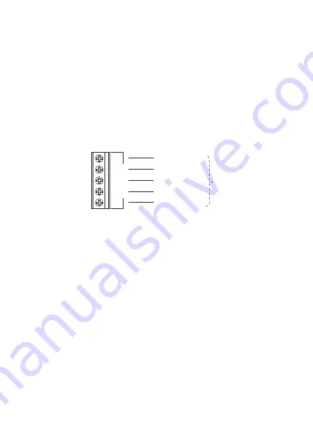
Figure 4 shows the wiring connections at the keypad. Do not connect the yel-
low wire.
Fig. 4.
12V 0V D0 D1 LED
EXT
READER
BLUE (LED)
WHITE (D1)
GREEN (D0)
BLACK (0V)
RED (12V)
External
Prox
Reader
KEY-KPZ01
Note: Do not connect
yellow wire.
External Prox Reader LED
The KEY-EP has a built in LED that can glow for 10s to indicate that the system
has set. This LED mimics the action of the LED under the “A” on the keypad as
follows:
In a part setting system the LED glows for 10s when the system enters Full
Set.
In an i-on30EX and i-on40 partitioned system the LED glows for 10s when
Partition 1 enters Full Set.
The jumpers in the keypad do
not
control the function of the LED in the KEY-
EP.
Enabling The KEY-EP
The KEY-EP must be enabled from within the control unit’s Installer Menu. Please
read the relevant Engineering Guide for the control unit, availble at www.coop-
ersecurity.co.uk.
Using the KEY-EP
The KEY-EP can be used to complete setting outside the protected area, or un-
set the alarm system before entering the protected area.
To use this feature enter the Installer Menu on the control unit and:


